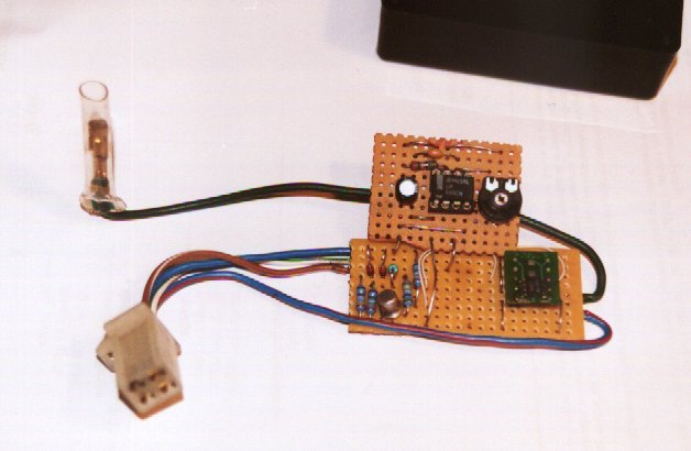 |
Here is a shot of the prototype. Note that the only
reason it is on two boards is that I ran out of spare prototype board to
do this on one!! The connectors are from the old bike loom. |
The Yamaha R1 is fitted with an EXUP valve. This is a Yamaha specific invention designed to improve torque at low to medium revs. It works by placing a small "flap" in the exhaust collector. This flap can be rotated to reduce/increase flow through the collector. When reduced the back pressure is increased and the wavefront at lower speeds can be reversed to improve extraction. The control of the EXUP valve is achieved by a small servomotor which sits on top of the bike engine. This links to the valve by two push-pull cables. The servomotor is controlled by the CDi unit directly.
All race R1s and after-market exhausts remove the exup valve. The worth of the exup is contentious at best - many bikers believing it is a marketing gimmick, whilst others praise its benefits.
When confronted with the question of "keep the exup or not?" I looked at the race bikes. The engine installation in a car is far nearer to that of a tuned race bike than a standard road bike. It has a different inlet system (no airbox), a different exhaust, a different silencer and of course, radically different engine load characteristics due to the cars weight. With these things in mind I elected to have no exup valve in my exhaust system.
At first you can think that if I have no valve then I do not need the servomotor either. I can unplug it/leave it out of the loom and all will be well. Err... nope. The exup operation is tested by the CDi unit when the engine loom is first powered up. If it doesn't find a working exup servomotor it will issue a fault-code. This is registered on the tachometer every few seconds (it drives the needle to 7000rpm and holds it there a few seconds). This fault code is also thought to limit the bike to one specific ignition map. The worst thing is that the fault codes continue to be generated even when the engine is running. This results in the tacho needle "dancing" up to 7000rpm every few seconds! To say this would be off-putting is an understatement.
So we need to do something about this.
Do we:
a) Buy an exup servomotor and leave it "spinning-away" in the engine bay? (I
did not have an exup servomotor as it was an "optional extra" for my
breakers-yard engine package. They cost around £50 s.h. in the uk). So this was NOT an
option.
b) Bodge the connector to trick the CDi into believing the servomotor is present using
fixed resistors.
c) Buy an electronic gizmo box from the US for $99. As an electronics engineer I regarded
this as a non-option. $99 buys a LOT of electronic components.
d) Develop my own gizmo box.
One R1 list/forum stated that you could get around the problem using some resistors in the loom plug to "trick" the CDi into believing the exup servomotor is plugged-in. This is rubbish. If you try it you will see that the fault code is maintained. If you actually think about what the CDi is doing you can see why. The CDi is trying to see if the servomotor or its built-in potentiometer is broken. If you put a resistor across a couple of terminals you are telling the CDi that the exup is stuck i.e. it is not functional. It is thus understandable that the CDi issues a fault-code.
Having decided to develop this I decided to measure the various signals on the
exup-servomotor loom. The design of the servomotor is pretty simple and is in fact a
classic servomotor with feedback control to the CDi
The B/Y and B/R wires look like they power the motor so these were the first wires I
looked at. What you find is that these are wired straight across a dc motor. They are
energised in turn, with the opposing wire being earthed. Thus the motor is rotated first
in one direction, and then in the other. I saw that the B/R wire gets driven to +12V
almost instantly power is applied to the CDi. As it turns back to 0V (after 0.5sec or so)
the other wire, B/Y is driven to +12V for around 2secs. After this time both are powered
down and the CDi concludes no exup is present and starts its fault-codes.
So we now know that these wires power the motor. The others are obviously for the potentiometer feedback. A quick check with a multimeter will tell you which wires are used here. You find:
Blue - +5V output from CDi to power the Pot.
Black/Blue - 0V (never driven and buzzes out to earth)
White/Red - floats (will not drive current) at 4.5V - the feedback input
Having seen the pulsing of the motor wires at the start we know that the CDi is trying to exercise the servomotor across its full extents. We know the time it takes to do this and we know that this will result in a varying resistance as it happens.
This gives us the design brief for the gizmo as we now know signals, times and function required.
There are a dozen ways to solve the problem but the most elegant is to use a
digital-potentiometer chip.
This can be setup to move the resistance up and down with time. I used a Xicor digital-pot
for my design. The circuit is shown below:
The circuit operates by monitoring the two signals that would normally drive the dc motor. When one is ON you want the resistance to go UP. When the other signal is ON you want it the resistance to go DOWN.
If you look at the datasheet for the Xicor part you can see that you can use the device as simple up/down resistor very easily. If you pick out the logic control lines you get the following truth table:
| /CS | U_/D | /INC | Action |
| 0 | 1 | 1 -> 0 | Resistance UP |
| 0 | 0 | 1 -> 0 | Resistance DOWN |
If we now put in our control signals that would normally drive the dc motor we get a full table.
| B_R wire | B_Y wire | /CS | U_/D | /INC | Action |
| 0 | 0 | X | X | 1 -> 0 | No R change |
| 0 | 1 | 0 | 0 | 1 -> 0 | Resistance DOWN |
| 1 | 0 | 0 | 1 | 1 -> 0 | Resistance UP |
| 1 | 1 | X | X | 1 -> 0 | Don't care |
Some conditions are shown as dot-care (X) as these shouldn't occur in our system. These allow the logic to then be determined.
The U_/D can be driven directly from the Blk/Red signal direct (once the signal is "potted-down" to prevent damage to the Xicor part.
The /CS must be driven from a combination of the two lines. The function is actually a NOR function. This is implemented using diode/transistor logic.
The /INC line is provided by a free-running clock. We only need to count up 100 steps (pot spec) in 2seconds. This yields a clock frequency of 50Hz or so. This was provided by a simple 555timer IC!
The circuit was found to work 1st time! The CDi really believes the exup servomotor is plugged in! In normal operation it will issue commands to the gizmo which will faithfully modify the resistance as required.
If you have some electronics skills you can make one of these units for your bike or car for just a few pounds (£). Use the circuit diagram and the prototype picture as guides.
|
Here is a shot of the prototype. Note that the only
reason it is on two boards is that I ran out of spare prototype board to
do this on one!! The connectors are from the old bike loom. |
You are free to use this design for your own personal benefit. You are NOT entitled to use this design as a basis for a commercial product. If you wish to do this you MUST contact the author and ask permission.
I am in no way responsible for anything that happens with you using/reading this article. If you fall off your chair - that's down to you. If you burn yourself soldering - that's down to you. If you blow up your engine - that's down to you. Anything else, yep, you guessed it - that's down to you!