What Parts Do I need?
Here is an attempt at a full-list of what you need for a bike-engine installation. Use
it as a template to present to a breaker/dealer. This may help you from being
messed-about for parts you had not thought of!
Some parts may or may not be required depending upon the extent of the loom etc used from
the donor car.
Parts from the Bike
| Engine |
|
Electrics |
 |
Main unit complete with cylinder head (doh!) - Ensure it has
an engine# if you want to easily register it with DVLA |
|
|
Main wiring Loom (full and undamaged if you want to use it
easily) |
|
Starter motor |
|
|
Main switch/Fuse and relay |
|
Starter motor leads |
|
|
Starter relay |
|
Generator |
|
|
Coil Packs and LT/HT wires |
|
Clutch lever |
|
|
CDi (ignition) unit |
|
Engine mount bolts (useful if they use weird thread pitches
like Yamaha) |
|
|
Regulator/Rectifier unit |
|
Engine sensors (oil level, tacho, speedo, neutral sw...) |
|
|
Fusebox |
|
|
|
|
Relays |
| Carbs - all 4 |
|
|
Instruments (speedo is probably not useable) |
|
With throttle/choke/idle adjust linkages |
|
|
Exup-servomotor and wire cables (YAMAHAs only) |
|
Trumpets to get into airbox |
|
|
|
|
Clamp screws and rubbers to hold them to inlet |
|
Pipework |
|
Fuel/air breather pipes of the CORRECT bore, preferably with
clips |
|
|
Fuel pump and fuel lines to carbs/tank |
|
Throttle pot sensor |
|
|
Oil cooler and pipes |
|
Airbox/Air filter unit? |
|
|
Radiator (CORRECT one please) with thermal switch/sender |
|
|
|
|
Rad Fan |
| Others |
|
|
Rad Header tank and pipes |
|
Gear shift lever arm |
|
|
Cylinder head top pipes including thermostat if fitted there |
|
Exhaust manifold - useful for downpipes mainly |
|
|
|
|
Exup valve (YAMAHA only) |
|
|
|
|
Sprocket from Gearbox output |
|
|
|
New parts required
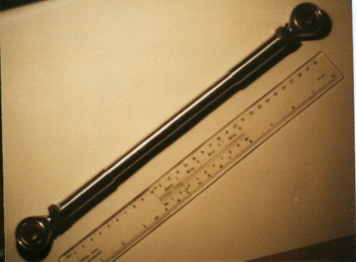
Propshaft 2-piece and central support
Speedometer - some bikes still have mechanical drive, most are electrical
Output sprocket from gearbox - requires adaptation/fabrication
Engine mounts - requires fabrication
Gear linkage - either mechanical rods and/or solenoid operation
Reverse system - mechacnical reverson, electric Heath-Robinson or Fred-Flinstone
Special Parts
Engine Mounts
Bike engines are mounted "hard" in bike-frames, with no rubber mountings.
In car chassis's it is customary to use mounts. Fisher Sportscars use rubber
suspension bushes, while other manufacturers use none.
Each engine is subtly different but the basics of mounting them is the same. Engine
mounts require triangulation to make the engine rigid.
You will need to fabricate the mounts from steel or aluminium depending upon the tools
you have available.
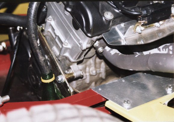
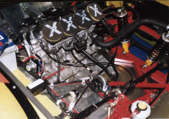
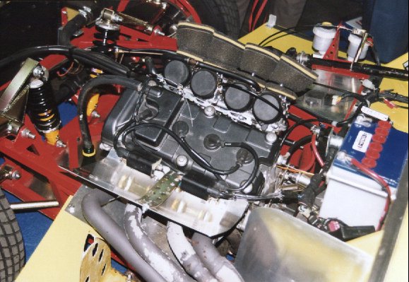
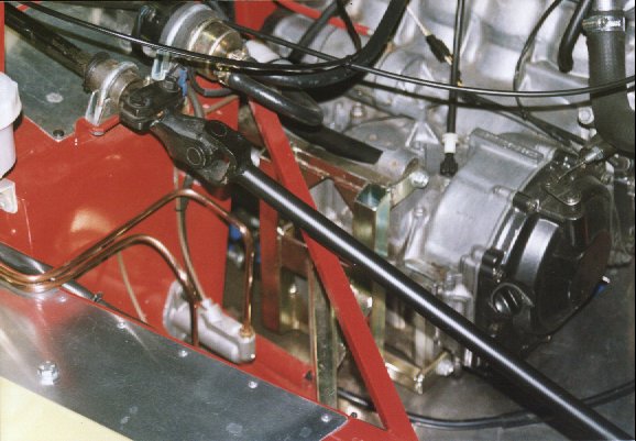
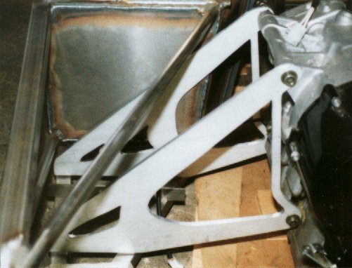
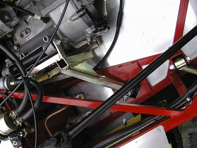
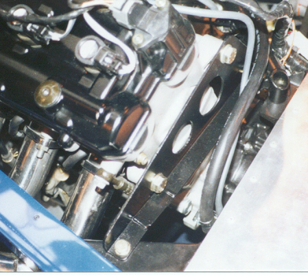
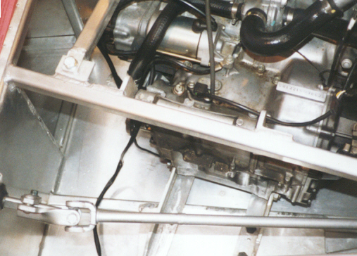
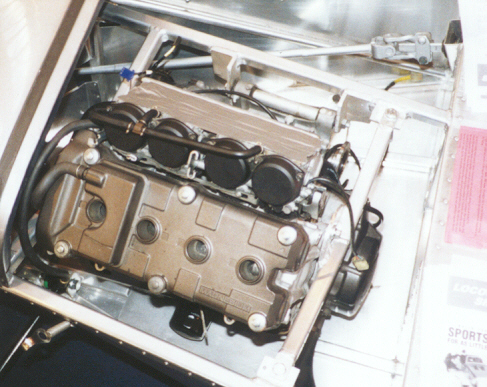
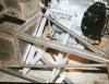
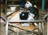
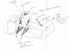
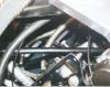
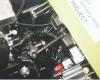
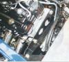
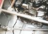
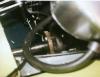
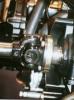
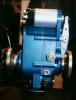
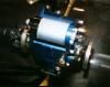
Here are some photos of the Fisher Fury Fireblade steel engine mounts taken at the
Donnington Show 1999.
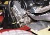
Front Engine mount: |
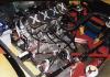
Gearbox side |
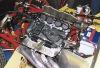
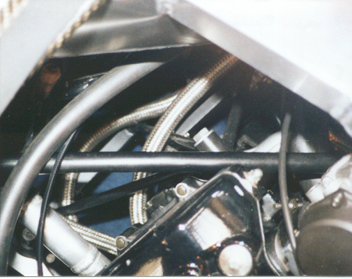
Overall engine installation |
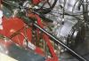
Righthand engine mount |
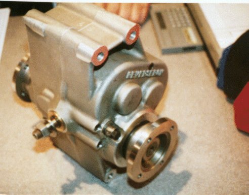
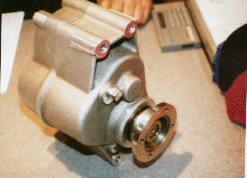
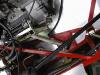
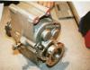
Here are some more pictures from Ruari Coles R1 Engined Striker. These are made from Dural
and are rather sexy!!!
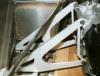
Ruari Coles R1 Engine mounts
A Sketch of Ruari's engine mount system has been kindly provided.
Ruari Coles R1 Engine mounts Sketch (Copyright R.Coles 2000)
Some other sketches of non-Sylvas.
Caterham Blackbird Front mount
|
Caterham Blackbird Rear mount
|
Fisher Fury-Blade
|
Westfield Hayabusa rear mount
|
Locost Blade
|

Locost Blade
|
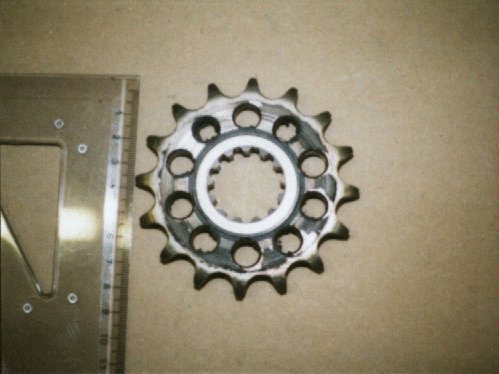
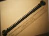
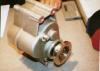
Propshaft & Drive
The output from the bike gearbox is a splined output shaft. Ordinarily the main
chain-drive sprocket fits onto this and a locknut keeps it in place.
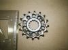
R1 Sprocket - Small eh?!!
|
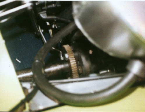
Caterham first Sprocket on Doug Newmans GoldArts Car
|

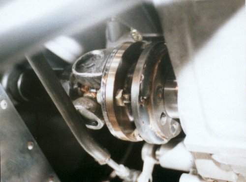
Westfield Welded Sprocket
|
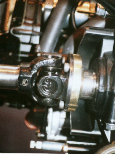
Caterham Prop-plate Nice!
|
Dashboard Instruments
A bike instrument binacle typically consists of the following displays:
- Analogue Tachometer reading up to 14000RPM
- Speedometer (either digital or analogue)
- Oil low-pressure light
- Water temperature gauge (either digital or analogue)
- Neutral light
- Indicator/main beam lights
Bikes do not usually have fuel gauges – but sometimes have a low-fuel light.
Standard car gauges can generally be used with one or two exceptions.
- The speedo drive comes either off of the bikes front fork or from its gearbox. Due to
the size differences between bike/car tyres/diffs the speedo will need recalibrating. Most
bike speedos cannot be recalibrated. You are then faced with a choice of buying a
"proper" car electronic speedo that is re-configurable, or using a pushbike
computer. The commercial units are available from Stack etc and cost from £100 upwards.
Bike computers are available from Sigma, Cat-Eye etc and cost about £15. This is for a
top-of-the range model with resetable odometer, stop-watch timing etc etc
- The tacho must come from a bike due to the higher RPMs experienced. It MAY be possible
to feed the tacho generated on the bike engine directly into the tacho. Alternatively the
CDi unit may generate an RPM output separately.
- The standard car fuel tank, sender and gauge can be reused.
- Gear display. It is quite tricky in a car to remember which gear you are in when you are
unused to sequential shifts. For this reason a gear-display LED is a nicety. A unit is
available from the author to do this function. It relies upon two reed-switches mounted on
the gearshift linkage to inform the display when a gear has been changed. Alternatively if
you are using the fully electronic gearshift mechanism the display is included.
Gearchanging
All bike engines feature a 6speed sequential box as standard. Gearchanges on a bike are
accomplished by pressing down on a lever with the left foot, or lifting the lever with the
foot.
Manual gearchange
Implementing a gearchange lever for a Sequential gearbox in a car is relatively
straightforward.
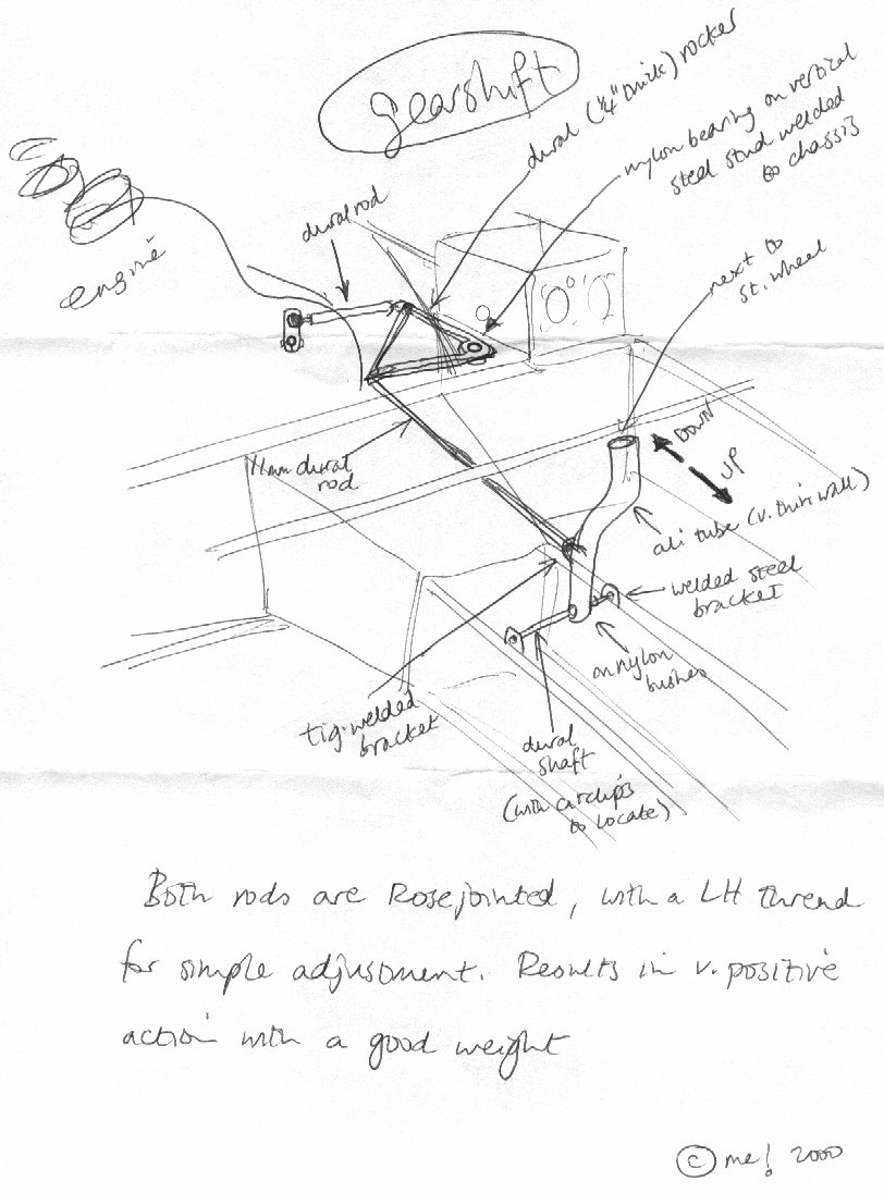
The basic principle is to use a vertical rocking lever sticking-up out of the tunnel and
use a forward pushrod to transfer the motion towards the engine. A bellcrank can then be
used to lift or drop the gearshift lever on the engine.
A sketch of this is shown below (courtesy Ruari Coles):

Ruaris Gearchange Mechanism (Copyright R.Coles 2000)
Electronic gearchange
Due to the simple nature of the change lever (just up or down) it becomes easy to see
an electronic solenoid actuated system.
Commercial system
There is a commerical offering called KlikTronic. This was originally designed for
racing bikes but works fine for cars. The system is based around an electronic control box
and a two-way push-pull solenoid.
The system is robust and was designed to cope with big American bikes with very heavy
shifts.
The system is available from "??" and costs £320+vat/p&p.
Home-Made system
A home made system is easy to design based around some cheap solenoids. It costs a tiny
fraction of the price (around £20 to £40).
What you need:
- 2 Solenoids
- A bracket to hold them to the engine casing.
- A nut/bolt and some washers to interface to the solenoid acutators.
- Some cables and/or electronic control box.
The Solenoids
The solenoids must be powerful but fairly small. After some experiments the ideal
solenoids were found to be the type that sit piggy-back on pre-engaged starter-motors. I
managed to buy two starter-motors from a 15year old SAAB 900 for just £7.50 each. Once
removed from the motor assembly and cleaned up they looked as good as new. These solenoids
are very powerful and draw around 12A and 12V when engaged! They also have a nice long
1" throw on them too. This is great value compared to buying new solenoids from
Maplin/CPC/RS etc as these typically cost twice the price for a quarter performance!
Mounting
Once the solenoids have been sourced they must be mounted to actuate the gearshift arm.
The solenoids are pull-types and must be arranged one above, one below the lever (or
one at each side if the lever is rotated through 90degrees).
Some solenoids (SAAB included) have retention springs inside which push the actuator
shaft out normally. Thus to arrange the solenoids we must have them opposed and pushing
each-other in about half way. This is so that when one solenoid pulls the actuator on the
other springs and moves. If the solenoids were mounted to give their full throw when one
pulled the other would have its actuator yanked hard and not move!
Finding the correct position for the solenoids in relation to the shift-lever and
engine mount holes is a trial-and-error thing. You only need to concentrate on one at a
time as the other is a mirror image.
Note that solenoids seem to have all sorts of different actuator shaft outputs. Some
have just a plastic rod-end (avoid) while others have a nice sturdy steel actuator loop
(SAAB – good).
Our actuators will have to be attached to the gearshift shaft via a bolt of some type.
The steel actuator output is too big for a normal bolt and so to make the action smooth it
is best to weld on a penny-washer to the actuator end. The link through the gearshift
shaft is then a simple bolt.
To hold the solenoids in place a bracket will be required. There are some convenient
bolts/holes on the bike-engine casing near the gearshift shaft and it is assumed that
these are to be used.
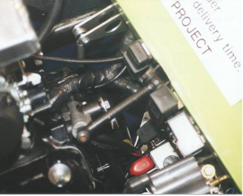
Solenoid Positions
Wiring it up
So now we have the solenoids mechanically fixed we need to look at the control of them.
For the uninitiated a solenoid is simply a coil of wire in a ferrite former. This is to
provide a concentrated magnetic field when a current is applied to the coil. A law of
physics states that if current is passed through a coil of wire a magnetic field is
generated within the coil. If a ferrite core is then positioned in the coil the magnetic
field will "drag" the former along and linear motion is seen.
The coil will draw quite a large current when the voltage is applied. From 8Amps to
around 15Amps with some solenoids. It is inadvisible to route cables directly to
dashboard/steering-wheel switches due to this requirement. A better system for direct
control would be to have the dashboard/steering-wheel switches trigger relays which can be
mounted near to the solenoids. This is shown below:
Diagram of basic relay controlled Shift
This method still relies upon the driver understanding how to operate a bike box. I.e.
the gear-order is one shove down to first, then subsequent pulls-back for 2nd,
3rd etc. Going down in gears is the opposite.
There is also a problem getting neutral. On a bike to get into neutral you do a
"gentle" lift/press of the lever when in 1st/2nd gear
respectively. To translate this to button presses requires a "tap" of one button
then the next to only part-move the lever.
To obtain a "pure" up and down gear functionality on the steering-wheel it is
necessary to employ a controller box. The one that I have designed is based around a PIC
microcontroller with some solid-state FET relays. This has the advantage of allowing the
tricky neutral "taps" to be pre-programmed and also gives an easy indication of
which gear you are in via an LED display on the dashboard. The development of this box is
way out of reach for anyone who does not design electornics for a living and so will be
discussed no further here. The author may be in a position to sell these control
boxes once their function has been proven.
Reverse Gear
Bike engines do not have reverse gear (apart from the enormous Honda Goldwings). So how
do we get the car to go in reverse?
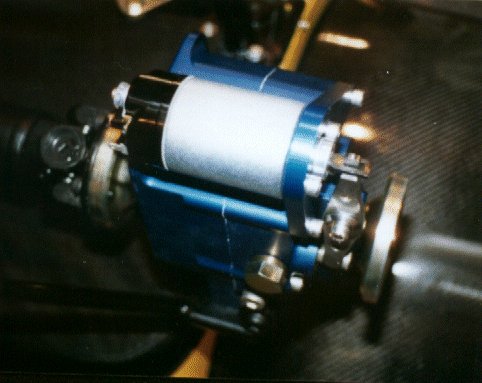
Commercial Boxes
There are two commercially available systems on offer.
- The first is the "Reverson" and is the system offered in F27, Fisher and
Westfield cars. It is a small box which sits in the transmisison tunnel and interfaces to
a split prop. The unit contains a system of gears that normally allows direct coupling of
the input and output shafts. There is a small lever on the side – when pulled this
brings a gear into play which has the effect of reversing the output shaft direction.
The Reverson is available from "??" and costs £??+vat
Reverson
- The second version is almost identical to the Reverson but also features a piggy-back
solenoid for reverse selection via a dash-mounted button.
This is the unit used in the
Caterham Blackbird cars and is thought to be rather more robust that the Reverson box.
The box is available from "??" and costs £??+Vat
BlackBird Reverser
-
BGH Geartech have a similar unit. It can be mounted in 3 ways and
has an extra handle position for neutral (i.e. props will be independant).
It costs £520 incVat and weighs 10KG. It has been designed to cope
with 250bhp (nitrous) bike engines.
- The great Ron Champion has an offering originally intended for use with his fireblade
locost chassis.
This is for De-Dion rear ends only. You put a large cog on the diff-input
flange and mount a starter motor above this bolted on a bracket on the diff.
This could possibly be done with a live-axle car but may lead to vibrating
loose etc.
Home-Made Solutions
Other solutions for reverse are electrical – relying upon an electric motor to
propel the vehicle backwards while the engine turns over in neutral.
This could be done by using some form of gear on a propshaft and a mating gear on the
motor. To eradicate losses it is important that the gears are not permanently in mesh.
An ideal mechanical setup would appear to be a small pre-engaged starter motor. A dash
button can be used to separately control the solenoid action to mesh the gears, and then
the starter motor drive can be controlled by a box of electronics by using PWM techniques.
There are some major problems with this idea though:
- The ideal place for the gearbox cog is on the output shaft of the gearbox. Due to the
size constraints of the engine this limits us to approximately a 10cm gear. This does not
give enough clearance for a starter motor to sit adjacent AND allow the propshaft past.