


Name: Ruari Coles.
Kitcar history: Fiddled with VW-based ACM Bonito while at school, built an SSC Stylus with Dad in 1996-7 and now doing this. Started research in March 1999 (when there were hardly any bike powered cars around....). Have been lucky enough to spend the last few summers working at TVR (three times), Reynard (on Mondeo BTCC and Panoz) and TWR (on Clio V6 project).
Why build this car?: Final year degree project for an MEng at Oxford University, meant
to be 40% of year's work. Being done on behalf of both Sylva and Tom Lowther (one of
their customers). Sylva have provided the chassis (18swg) and Tom has provided all
the necessary R1 bits. Tom will eventually keep the finished car. The deadline
for my report is the beginning of June, by which I hope to have a complete (panelled)
rolling chassis with as many extra bits done as possible.
Where?: Work being carried out in the Oxford Engineering Dept.'s Osney Mead research
labs - on the first floor, so the car will need to be craned out....(!) Practically
every tool/machine available (if not on site then a mile and half across town in the main
engineering dept.), and if I can't use what I need (or don't want to) then there are lots
of friendly lab technicians happy to do jobs for me.
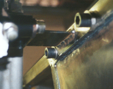
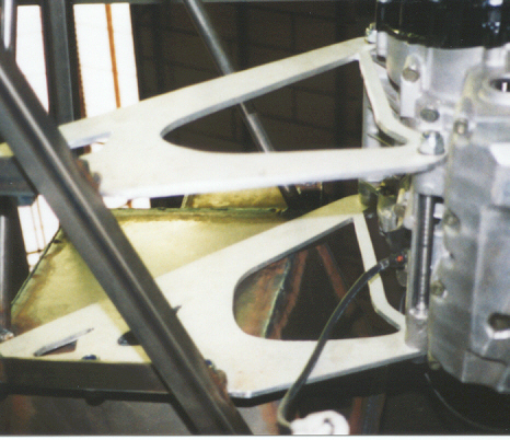
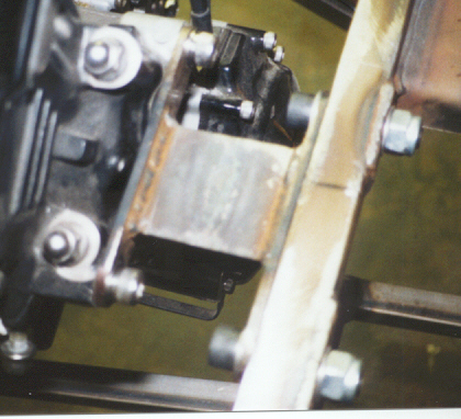
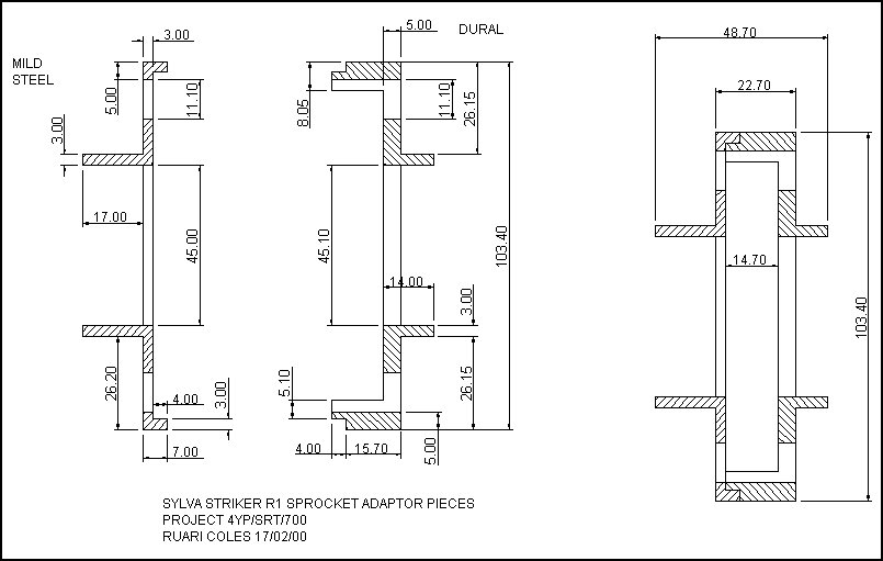
The Engine mounts are fabricated from Dural Plate and mild-steel.
|
Engine Mount Sketch | |
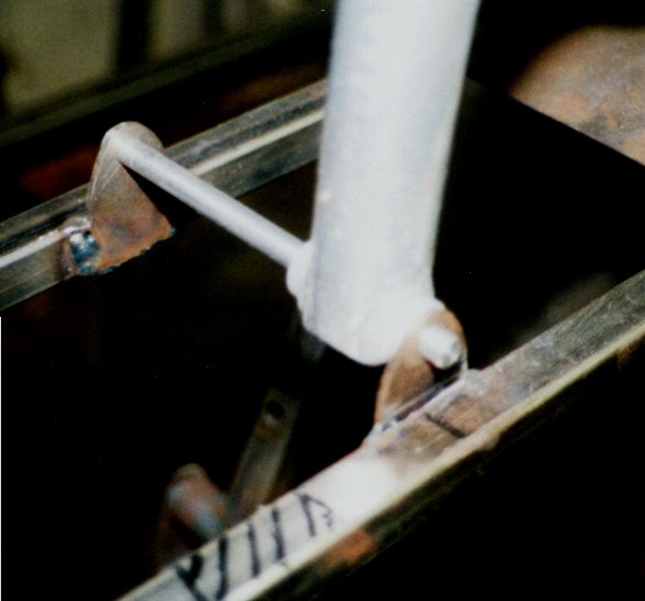
Rear restraint viewed from below |
|
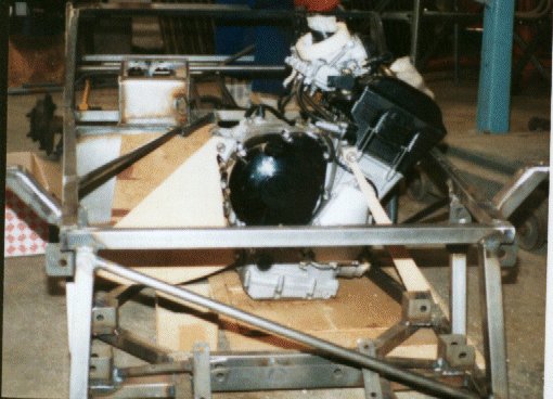
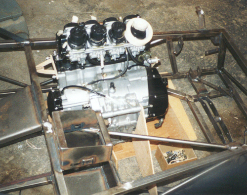
R1 Engine fitted with temporary wooden engine mounts (FRONT) | |
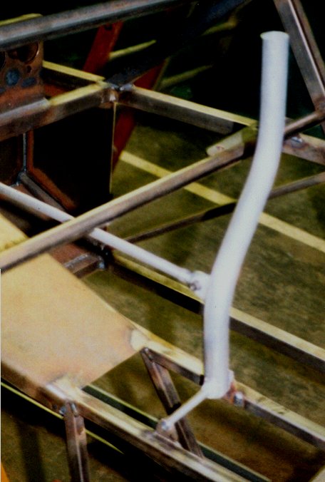
Front strut in place |
|
R1 Engine fitted with temporary wooden engine mounts (REAR) | |
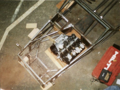
Engine underside view |
|
R1 Engine fitted with temporary wooden engine mounts (TOP) | |
Engine Installation viewed from the Right-hand side |
|
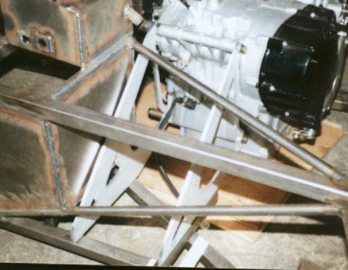
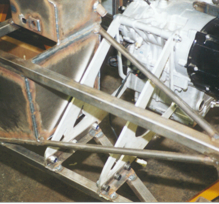
Main Mounts | |
Main engine mounts viewed from below |
|
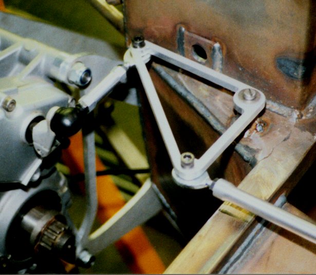
Detail of Main Mounts. Designed to take all loads by themselves. Made of 1/4" Dural Plate. | |
Main engine mounts viewed from the front of the car |
|
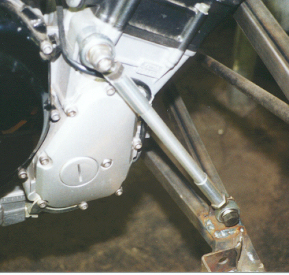
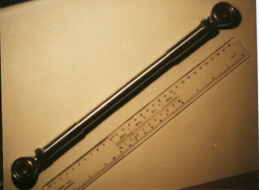
Front Engine Mount Strut. One bearing has a LH thread to allow tensioning by rotating the rod. | |
Main mounts from the drivers side of the car |
|
Oil Filter Clearance - enginbe must be high enough for filter to pass above chassis. Sump Bottom is approximately level with the chassis bottom. | Oil Filter clearance required | |
|
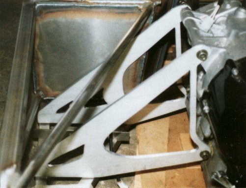
Rear restraint made from Mild Steel | ||
|
Rear restraint viewed from Above |
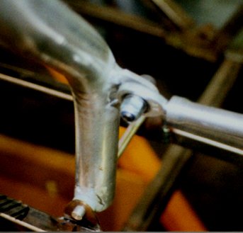
Here is a manual gearchange linkage. Due to the position of the gearshift arm on the bike-box a 90degree turn has to be made. This is achieved via a bellcrank system.
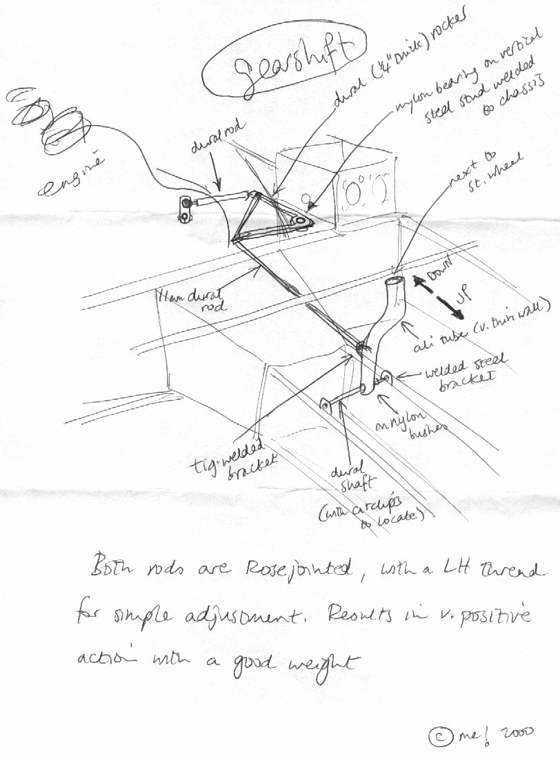 |
Sketch of Gearchange Linkage Mechanism | 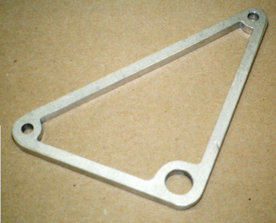 |
Gear Rocker - made from Dural |
 |
Gearlever | 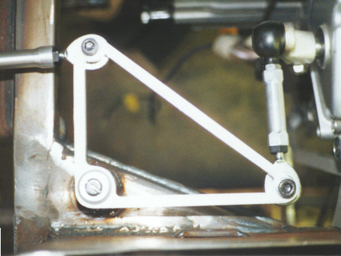 |
Gear Rocker from Above |
 |
Gearlever - base hinge | 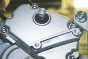 |
Gearchange Shaft on the engine |
 |
Gearlever - middle point | ||
 |
Gear linkage detail showing the rocker in place | ||
| Gear Linkage viewed from the front of the car |
New improved Gearchange linkage
| Improved gear-lever bracket using the reverser box bracket | Detail of the lever base bracket |
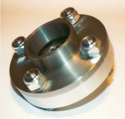
The sprocket drive uses the standard bike cog. It consists of two plates which
encase the cog and use drive bolts connecting through the "teeth" of the cog.
The smaller half is steel, the other dural, and the aim is to weld an MGB-type prop
flange/UJ directly onto the steel half. The sprocket can float 5mm, and the
extension out of the back of the dural half is a tight fit round the R1's fatter output
shaft bit (which rotates with the sprocket) to prevent any rocking.
 |
Sketch of Gearchange Linkage Mechanism | 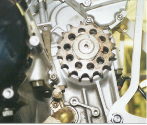 |
Gearbox output shaft fitted with bike sprocket. Note that the rubber within the sprocket has been worn away through machining! |
 |
Dural Plate | 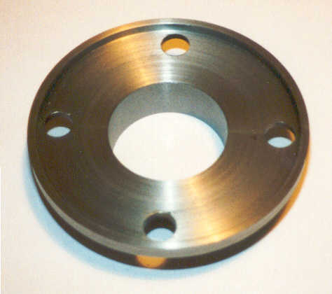 |
Steel Plate at the rear of the engine bay |
 |
Complete Assembly from Rear |  |
Complete Assembly from Front |
 |
Complete Assembly from Side! |
All the various welds on the props have been TIG welded. The UJ yoke shown stuck to the steel half of my prop adaptor is from the gearbox end of an Anglia prop (same UJs as the MGB) - with the long splined bit cut off you get left with a much smaller fitting as there's no big flange (as there is on both ends of the MGB prop).
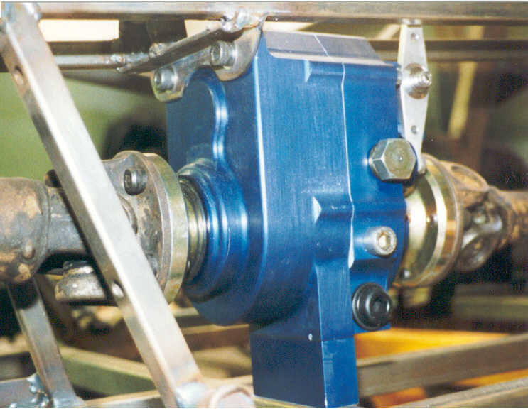 |
Reverser Box in position viewed from Car Nearside Front | 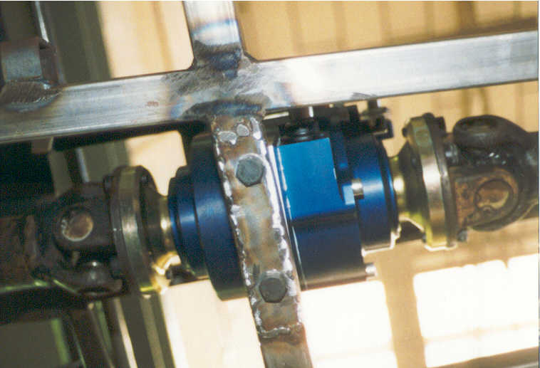 |
Underside View of reverser box |
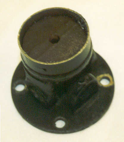 |
Escort UJ Before Machining | 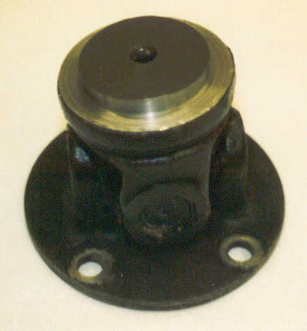 |
Escort UJ after machining! (to fit inside a smaller MGB prop tube) |
 |
The rear propshaft | 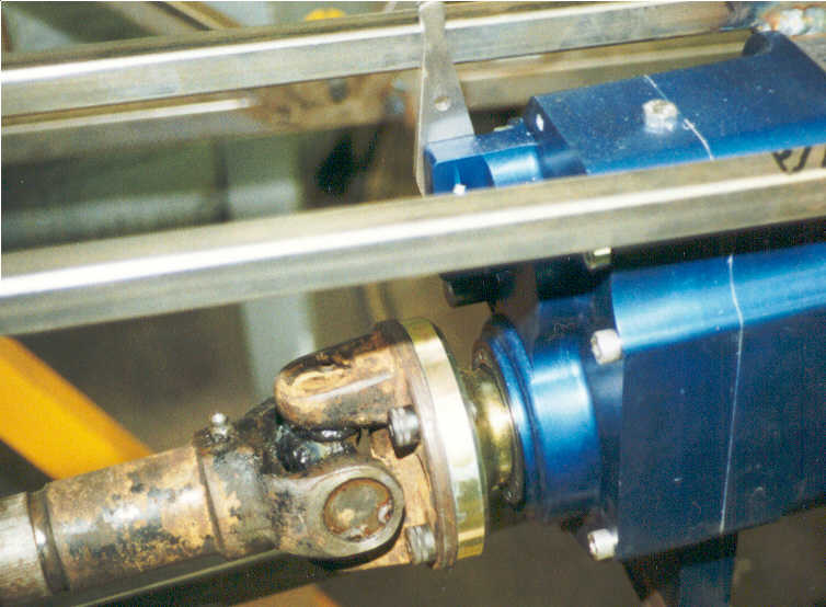 |
The rear propshaft attached to the reverser box |
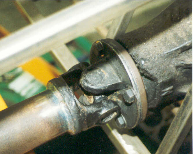 |
Rear prop and diff |  |
Steel main part of Yoke |
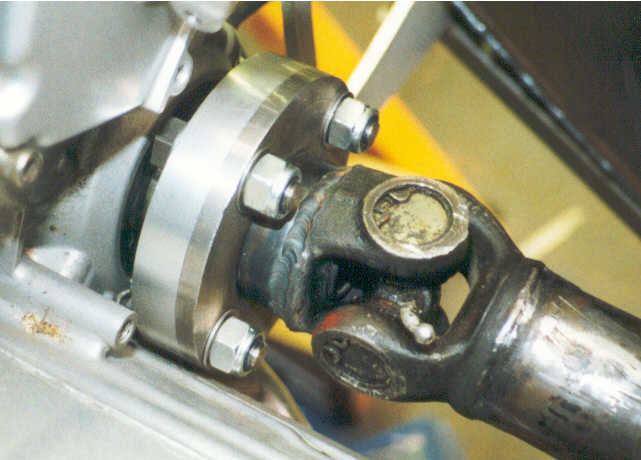 |
Completed Propshaft and adaptor plate in place |  |
Alternative view of prop in place |