Lincoln Electric MIG Guide (pdf document)
This is such a large area of the work I felt it needed a whole page.
If you have the bike manifold you may be able to make up your own by simply cutting and
re-welding sections. This is what I have tried to do.
The manifolds are made of
some stainless steel alloy so welding can be tricky (make sure you have stainless wire and
Argon/CO2 gas for a MIG welder).
If you are crap at welding (I am) here is a useful link to a site:
Lincoln Electric MIG Guide (pdf document)If you don't have the old bike manifold you will have to either buy a load of pipes and start from scratch, or bite the bullet and go to a proper exhaust manufacturer. Take the car with engine fitted to an exhaust specialist such as Custom Chrome in Nuneaton. They will make you a full set of pipes etc. The cost is around £400. Of course this cost is only have of it. You have to get the car there and back too - if you have a trailer/tow-car this is the way to go. If not car transporters cost around £100 a day. Gulp.
A half-way house is to measure up your own bends and get them just to fabricate the main down pipes. The method to do this is:
With regard to silencer you can either use a standard bike silencer or a car type. I have a large silencer originally bought for the noisy (112dB on its worst day) XFlow and I am using this.
![]() Feb 2001
Feb 2001
I was lucky enough to be given an old fireblade manifold by a fellow builder
that had tried to make his own manifold. He gave up after unsuccessfully trying to weld the stainless-steel fireblade pipes to his extra mild-steel
pipes.
The fireblade manifold pipes are almost exactly the same diameter as the R1 manifold pipes and they appear to be made from the same material too!
The system is a sort of 4-2-1 system. I say sort-of because the 2-1 bit is so short I think the gasses will "see" the junction as a 4-1 type.
The output from the final collector is a large bore tube that just fits inside my whopping 2.5" silencer bore! Luck or not?
Before trying to build up the manifold I elected to try a fag-packet
calculation to see if the pipe lengths would be ballpark.
The only equation I could find for this was in a Tuning the XFlow book.
L = 5100 x ED L is the primary pipe
length in inches from the exhaust valve head to collector
-----------
ED is the exhaust
valve duration in degrees from the opening point to TDC
RPM x
6 RPM is the peak power
RPM - 500
I did not have any timings on the cam in the R1 so I looked around for something similar. Need-For-Speed advertise hotter cams for the R1. These have exhaust cam figures for opening/closing of 50/22 degrees respectively. Other bike cams I looked at were milder with around 45/15 being typical.
I elected to use these figures (this is ballpark don't forget!). Putting the values in:
L = 5100 x (45+15+180)
----------------------
9500 x
6
=> 21.5"
A quick measurement of the original R1 manifold found the measurement to be about 25". Putting this figure back into the equation we arrive at valve timings of around 100degrees. Clearly this doesn't seem right so I must be adding too many parts. Comments from Gurus?
As I do not have the time to sort this out too accurately the safest thing is to try to make the pipes similar in length to that on the bike e.g. 25".
|
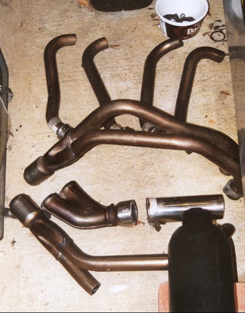
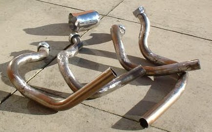
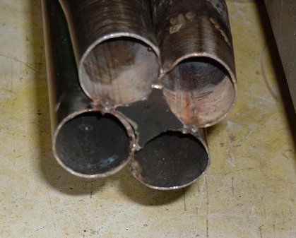
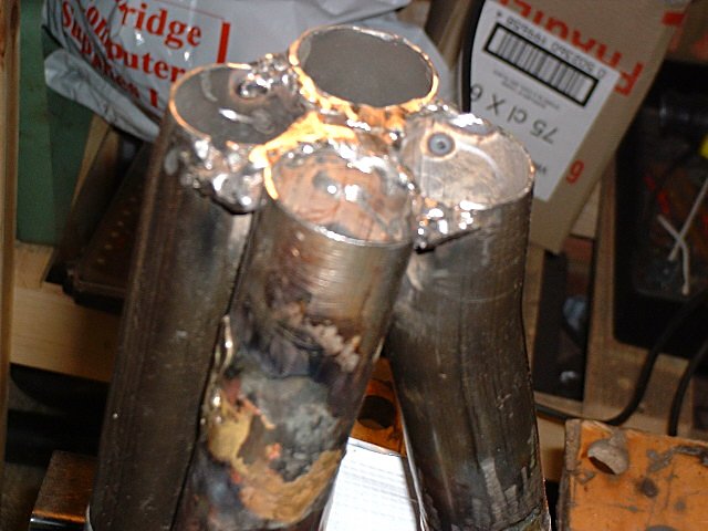
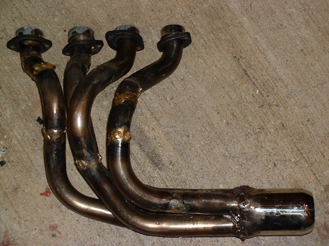
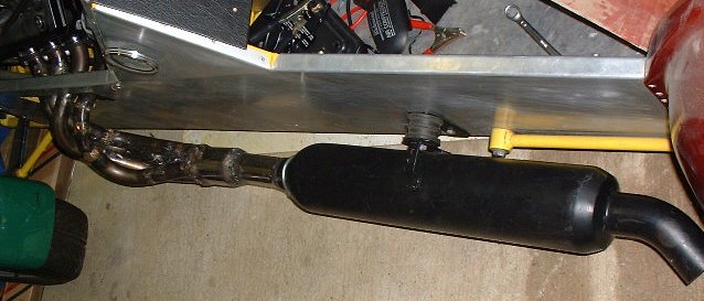
Raw materials to work with
At the top are the offcut R1 downpipes. Under these are the fireblade pipes and collectors. At the bottom you can see the end of the large (5" girth oo-er) silencer. |
First identify the materials. Mine were some sort of stainless-steel alloy (try a magnet). The pipes are all about 1 3/8" in diameter and have a very thin wall thickness (around 1mm).
At first I thought I'd start at the silencer end. I cut up the blade collectors and made these fit together. I positioned the silencer and offered the pipes up to the silencer. Mmm... due to the very long silencer and the generously proportioned blade collector pipes the ends of the collector pipes were about 4" from the engine head!!!!!! A re-think was required - the pipes would look like spaghetti if this collector was used.
So - assume a new collector is needed and go for a 4-1 system. It matches the R1 bike so we can go for the same pipe lengths (around 25").
Now what.... mmm.... have a cup of coffee....
Ok. So we should start at the other end. Make up a dummy
collector to at least aim the pipes in the right direction. For the first
pipe choose one of the straighter sections of header-stub. You will need
the more curvy ones later for the cylinders closer to the collector.
Look through all of the bends you have and start offering them up to the
car. This pipe is easy in that you are looking for a fairly direct and
close route. Make sure the pipe is a safe distance from the cars
side. I went for a 90degree type bend to start with. Get this into
position and mark up this pipe and the header-stub so that they can both be
cut. Top-Tip: Use a permanent marker pen to mark-up
the cut-lines. It wont rub off with handling!
Cut the pipes cleanly and put back onto the head. Use duct-tape
to secure the two together. If you measured/offered/marked/cut correctly
the pipe should be coming out of the engine bay and down the side of the car
almost vertically. Now do the next section of pipe. Aim to hit the
bottom of the collector nearest the car.

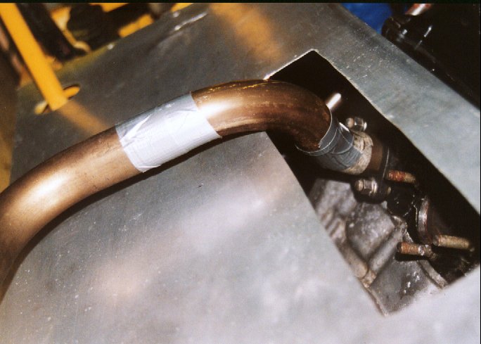
|
Lining up the first pipe. Start at this end.
The longest pipe creates the length to aim at. Checkout the pretend collector plate attached to the silencer. This is to give something to "aim" at when planning the pipes. This pipe should be nearest the car side and at the bottom of the 4-1 collector. |
Phew... first pipe done. You'll be feeling mighty pleased with yourself now ;-)
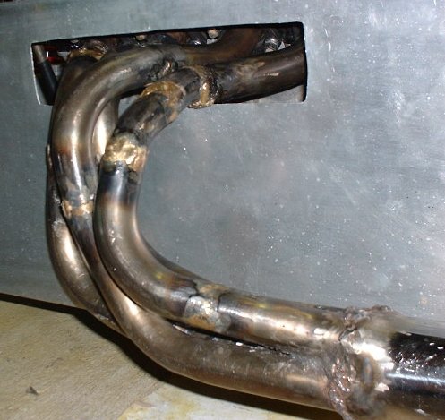
|
Detail closeup of the head, showing the first bend in the system. This pipe (cylinder 4) is made of three pipes. Minimise the number of sections in all the pipes - it's easier to weld then! |
Now for the next pipe.
You basically follow the same procedure for this pipe. It is of course about 3" nearer the collector so you are looking to try and get some of this length back into the pipe. This is done by making the header-stub point backwards towards the front of the car, and by swinging the arc of the pipe out further than the first. Again, duct-tape the pipe sections together. Note that the final lengths may look different. Until we get the collector this is ok - we can adjust them later. At this stage we are looking to get the pipe positions "about right".
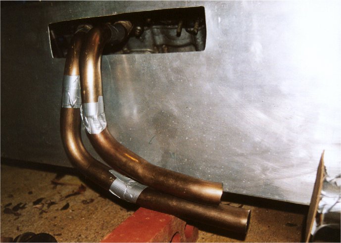
|
Second pipe in place. This actually turned out to be the shortest pipe in the bunch. It bends out and up to aid it's length. It joins the first pipe next to the car side, but above it. |
Well now we have two pipes in position and you should still have a good selection of bends etc.
Complete this method until all four pipes are made. See how the pipes nearest the collector move further and further away from the side of the car to get extra length into them. The last pipe is likely to be the hardest to achieve length on. It is nearest the collector and will require the most bends. At this stage your selection of bends will be limited too. Two of my pipes have 3 sections, one has 4 sections and the last has 7 sections. Whether this will affect gasflow remains to be seen. To get this last pipe to fit in you may have to use the grinder to cut an "unusual" angle between two pipes. Make sure the joints are as close as possible.
Top Tip: With all stages it is wise to keep bolting the pipes back to the manifold at every stage. It takes time but gives a better chance of a good fit.
The bends of the pipes, and detail of the head entries are shown below.
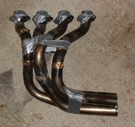
|
A top-down view of the duct-taped pipes. The pretend collector made from a pringles tin and some plumbing pipe offcuts is very useful, but I would recommend getting the final item before this stage if possible! |
|
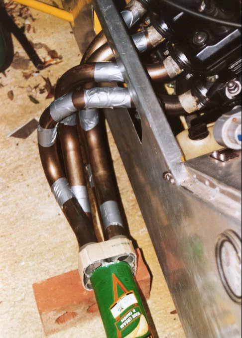
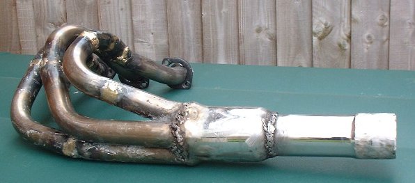
A side view of the duct-taped pipes. See how the
pipe nearest the silencer really has to bend out. This pipe was the
hardest to make, and has the most sections (6).
The bricks are exactly the right height under a Striker to balance the silencer and the collector - and align the height of the system! |
Now that the pipes have been duct-taped into position it is time to make structure more solid. Take each pipe off in turn, taking care not to bend them. Firmly position them on you welding bench and begin tack-welding them. For this you need to use a sharp knife to peel off strips of tape. Expose enough material to blob a weld across.
Welding Stainless-steel can be tricky. A good starting point for MIG is to be on very low power, low'ish wire-speed, use Argon/CO2 or Argon gas, and stainless-steel wire. Try some leftover offcuts first to get the machine correct. I used 3 welds per joint. If done correctly the pipes are now very strong and the tape can be removed.
|
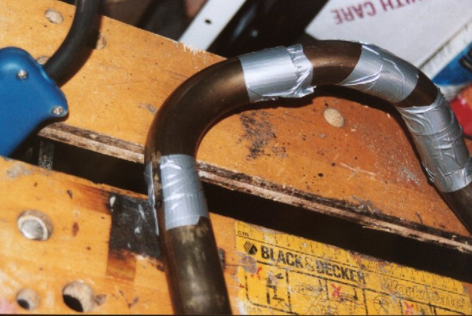
Tack welding the tubes. The duct tape holds the bend quite firmly. Use a sharp knife to strip sections of the tape off and tack weld at 3 positions around the joint. Try to maintain the correct positioning of the pipes, and try to achieve minimal gaps for easier welding! |
Top Tip: With all stages it is wise to keep bolting the pipes back to the manifold at every stage. It takes time but gives a better chance of a good fit.
Once you have tack-welded the
pipes bolt them to the head to check final fit.
|
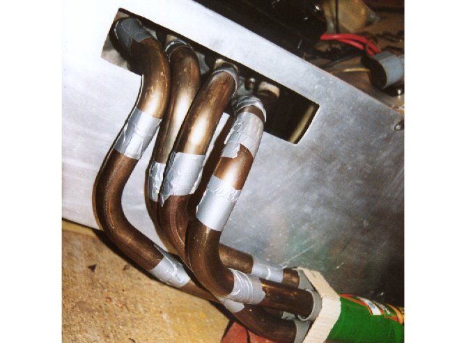
The four pipes in place. See how the pipes closest to
the silencer end must bend out and over the longer pipes. This is to
get the lengths as close as possible.
At this stage the collector had not been purchased and the pipes needed adjustment to make them fit. This is why we don't fully-weld them at this stage. You are likely to need to take some of the joints apart (use a saw or grinder) to reposition them. |
Once you have bought a collector the next stage is to trial fit the collector in position. I managed to buy one that required the pipes to be butted up together. This meant I had to modify the pipes (chop bits out) to make the ends join up.
If you can - get hold of the collector before you start work as this will remove one stage from your pipe cutting.
|
If you are not REALLY good at welding then this bit is best left to the experts. MIG Welding thin stainless-steel tubing with circular butt-welds is very, very, very difficult. |
Warning aside... I attempted it.
The material is very thin (about 1mm) so set that MIG down low! My Clarke150TE was set at 1-MIN with a wirespeed of about 4.5/10. Gas was either Argon/CO2 mix or Argon (when I ran out of the other!). Wire MUST be stainless steel. Experiment on the offcuts to get the "bacon" sound. It is quite hard to achieve I found.
The technique to use is not to try and do too much in one go. Run short seams (15mm or so) and try to work round each joint such that you are never heating the same area up for too long. If you do holes are likely to blow through.
I found the welding very tricky as I am quite frankly crap at it. I had trouble maintaining a constant distance from the weld. Some welds looked ok, others awful.
Once I had done the first round of welds I opted to leak test them. A basic test can be performed by rubbing soapy washing-up-liquid over the joints and blowing down the tube. Bubbles form where there are holes. It is not too accurate and is tricky to find the holes exactly. See below for a better method.
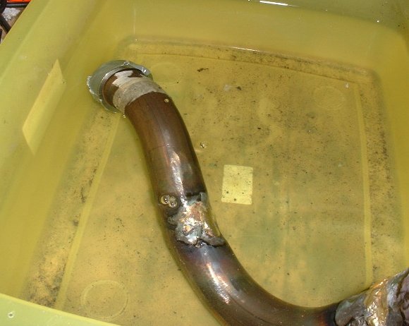
|
Leak testing the pipes in a washing-up bowl of water.
The technique I used is to seal one end of the pipe with Duct tape. You then submerge the pipe so that the joint you are interested in is underwater. Then hold the other end, put it to you mouth, cup your hands around it and blow. If you blow with increased pressure you will accurately see where the bubbles and hence holes are. Note that this is only suitable for stainless-steel etc, mild steel will rust! |
If you get them welded up by a Pro I would expect virtually no leaks.
All the joints leaked so I opted to try to "blob weld" them up. This was tricky as unless you get the hole spot-on you tend to form a ridge of weld adjacent to the hole. This doesn't fill the hole in and you just end up hiding it!
I then opted to grind the welds all flat and try again. I used a standard metal grinding disk in the angle-grinder to get the bulk of the metal off. I then used a flap-sander-disk to make them look a bit smoother. Once the grinding is done (warning: it creates an enormous amount of dust) then you can try welding the holes up again. Unfortunately it's very easy to get the metal very thin with the grinder. When the welding then starts it is VERY easy to blow holes. I ended up blowing holes in all of the tubes. I welded on patch plates around each hole.
At this stage I realised I was very very bad at welding :-(
After chasing my tail for a week and burning countless holes I decided to try a new tack.
Someone at work (Big Dave) mentioned brazing so I looked at this. Brazing is more like soldering than welding. You heat a joint up and melt in a lower-melting-point donor-rod. This "sticks" the two metals together. People think it is a weak joint but it can be pretty strong as molecular bonding does occur between the two metals.
I cleaned up the pipes so that all holes had patch plates, and I ground-down all of the joints so that the metal was as "flat" as possible. You can see from the photo that the pipes are shiny now. All oxides removed before brazing - this is very important.
|
Pipes ready for brazing. All cleaned up with just
small holes/cracks left to fill.
The collector is also pictured. |
I went over to Big Daves house and used his brazing kit. He has a proper Propane torch that can get big things like this hot.
Some quick calculations tell us:
I used brass which melted at around 900degC. Make sure you get the right flux for the job.
Brazing was quite good fun. It takes a while to get it hot and it is a bit tricky to see where to stick the brass rod. It doesn't go as molten for as long as it does in soldering so you have to be fairly accurate.
We tried to "seam" around all of the welds.
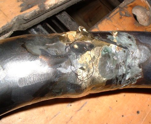
|
Pipes after brazing.
See the flux residue as the green coloured stuff. This sticks hard and has to be removed with a hammer (wear goggles!). |
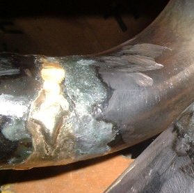
|
A good looking brazed joint.
See how the metal pipe has discoloured with the high temperatures used. |
Once all of the joints are done the pipes are left to cool and then the flux residues removed.
I leak tested the joints before and after flux removal.
Prior to the flux removal there were just 4 holes left in 4 pipes. After
removal there were 11 :-(
|
A hole in this brazed joint is clearly visible here. This must be patched. |
A second round of "spot brazing" was then required.
I tried a plumbers-brazing torch for this but this was pretty useless (Thanks to Cam anyway - www.deathwagon.co.uk).
So after that it was back to Dave's house for another round of brazing. After another couple of hours it looked like we had fixed all of the leaks. We didn't have much time and I had left all the flux/dirt on.
I got back to my place and cleaned the pipes up. Leak tested again all of the pipes still had holes!!! Damn.
At this point I was feeling very bored with the whole thing. My inability to weld correctly to start with was at the back of my mind :-(
I enquired with some local welders but none were really interested in looking
at the pipes. I obviously spoke to the wrong people, or they have enough
work on.
I also tried to hire some brazing gear. I called all the local places and
only HSS Hire shops could do it. They have a HSS weld-hire
"division" which distributes to all the stores. For a small
OxyAcetlene brazing setup (all they had) they wanted £39 a day.
Not bad I thought - "does it include the gas"? Err - no.
That's another £15 for the Oxygen and £30 for the Acetelene. You also
have to pay Tonys Cut (VAT) on that lot too. So £98 for a day. Err
- no I don't think so.
I eventually persuaded Dave to lend me the gear over a weekend which was a God-send.
That weekend I spent about 4 hours finishing the brazing of the pipes. You have to basically do the following for each hole:
Top-Tip: Do NOT dunk the red-hot brazed pipes straight into the water bath. This will cause the brazed joints you have just lovingly created to crack! More holes!
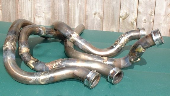
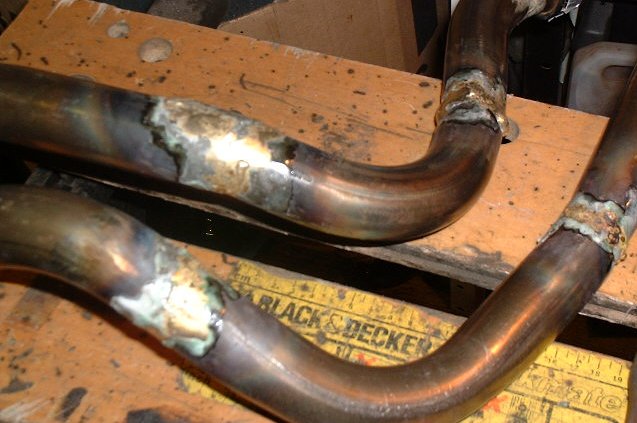
|
Finished Brazed pipes. Yes they're pretty ugly and at this stage I couldn't be bothered to sand down all the brazed joints for fear of making them "holey" again. They will look ok with a coat of paint - maybe. |

|
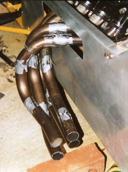
Fully Brazed pipes trial-fitted to engine. See how the pipes all come together as planned! Phew! |
In total I reckon about 9 hours were spent brazing these. Cost was about £18 for brazing rods and flux.
The next stage is to join the pipes together ready for the collector to be mounted on.
Just put the pipes onto the engine, arrange them as required and tighten the bolts all up fully. The pipes can be held together a bit better by the judicious use of Duct-tape. This makes the pipes less prone to moving about when you take them off the car to weld them up properly.
 |
Pipes tack-welded together. |
 |
Pipes tack-welded together with added Duct tape for support. |
You need to make a metal "diamond" for the centre and some triangular pieces for the outside edges. Use an offcut of pipe, cut it open and hammer if flat to get a new piece of metal.
You can make the patterns by drawing around 4 pipes on some cardboard. Cut out the pieces and use them as templates onto the metal. Cut out the pieces with an angle-grinder.
Top Tip: Try to make the pieces fit "inside" the pipe gaps as close as possible. It will make the welding easier. I didn't do this as I was in a hurry and I messed it up (see below).
Now fit these plates into the pipe end and weld them all up. You can use small pieces of Blu-Tak to hold the side-plates (it goes gooey and burns real quickly though so remove it once a weld has been made.
Take your time in getting the welds done here. I didn't and paid dearly for it.
|
Side and centre "plates" welded into position. |
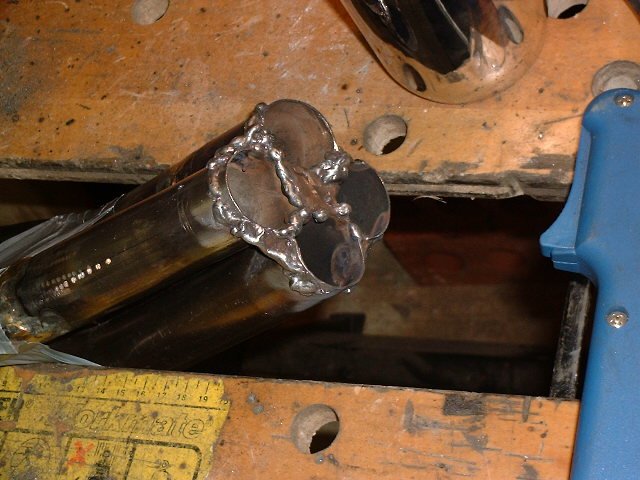 |
Fully blob welded ready for collector. |
You should have been testing the fit of collector etc as you were doing the above work. You now have to add a weld bead all around the edge of the pipes at the point where the collector will meet them. You will also need to trim down the plates you have welded on to give a snug fit of the collector over the pipe ends. Take your time on this one as it makes the final weld bead joining the pipes/collector easier.
It is worth checking fit again at this point - before you finally weld on the collector.

|
Trial Fit of Collector and silencer. At this stage
the collector is held over the end of the pipes with duct
tape.
Luckily my crude measurements to align all this were spot on. Check out the heavy duty silencer mount - an old gearbox mounted given to me by a local exhaust dealer for free! |
 |
Close up (unfortunately it's blurred like hell so try squinting ;-) |
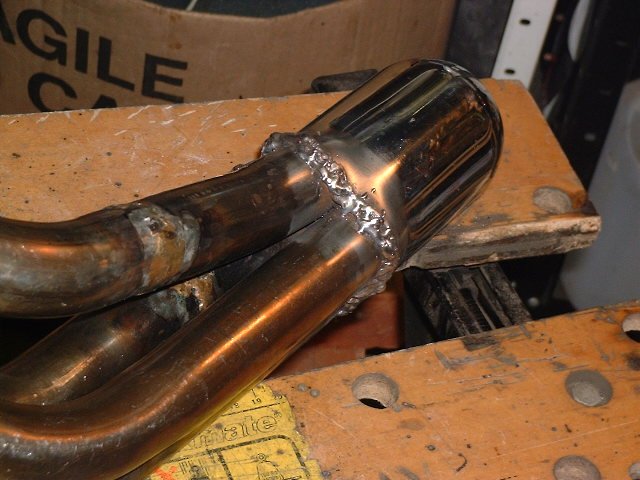
Ok. Now weld up that collector.
|
Collector welded onto pipes. The material is fairly easy to weld as the hole-blowing does not occur with the thicker metal and higher heat capacity of the completed assembly. |
Oh dear. They leak. And not from the outer edges that I can get to - no... from the middle. Damn.
This was due to me not making 100% sure that the diamond and triangle plates were welded completely. It was impossible to test and it caught me out.
You cannot braze the inner section as the heat capacity of the assembly is now huge and the propane torch wouldn't get the assembly hot enough. An OxyAcetelene kit may work. As I couldn't do this I had two choices:
I tried some Carplan Fire-Putty. It's tricky to apply down in the hole, and as it's not clean didn't stick too well. I cured it with a blow-lamp. I tried several times to get this to stick but it kept leaking. It did however ooze through into the collector to show me where the culprit holes were. I then tried welding blobs over these. It helped but there were still small holes.
I then tried standard bathroom silicon sealant after a tip from a fellow kit
builder (I cleaned the old stuff off first).
The stuff is allegedly more than capable of the high temperatures. This
stuff is very sticky and will cling to almost anything. It is quite
"thin" too so you can get it wedged down nicely. I did this in
several "layers" and found the best tool for the job was... my
finger.
After several goes with this I managed to stop it leaking. Phew. I just hope it doesn't burn off too quickly.
 |
Sealed up with fire-putty (internally) and silicon sealant
(externally).
A leak test finds that they don't. However the silicon sealant may "move" when proper heat from the engine is applied. |
Trial fit the system and work out the angle that the pipe needs to go into the collector to enable good clearance of the silencer and car-body. Use a wedge of wood to help get the gap correct.
Then tack weld the pipe in place. You can actually run quite a long bead as so much is exposed.
Take the pipes off of the engine back to the bench to complete the welding. You can leak test these easily. Once you have welded all the holes the pipes are complete! This material is 2mm thick so difficult to blow holes in.
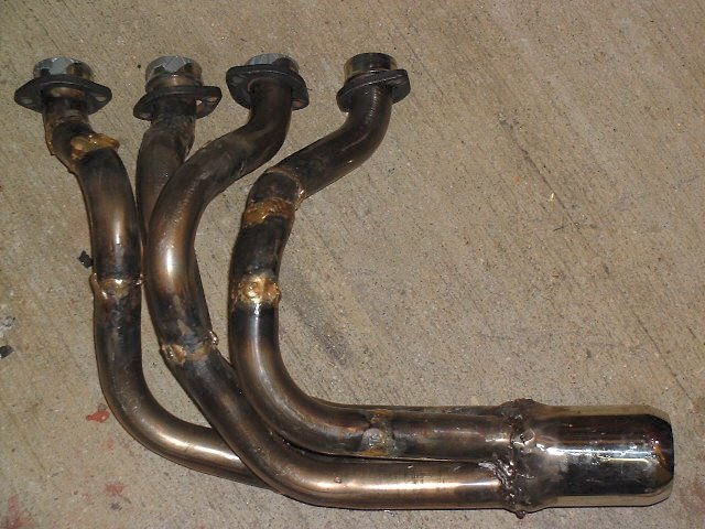
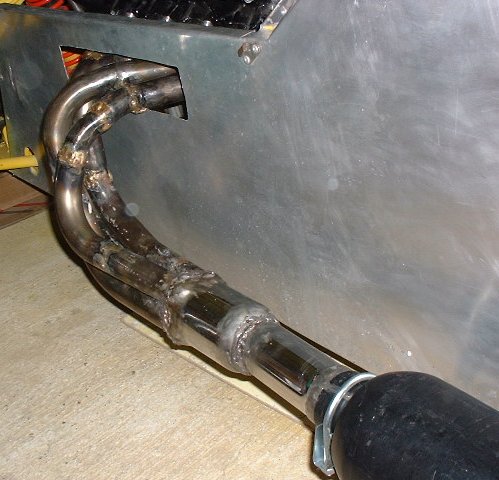
|
Finished Pipes |
 |
Finished Pipes closeup |
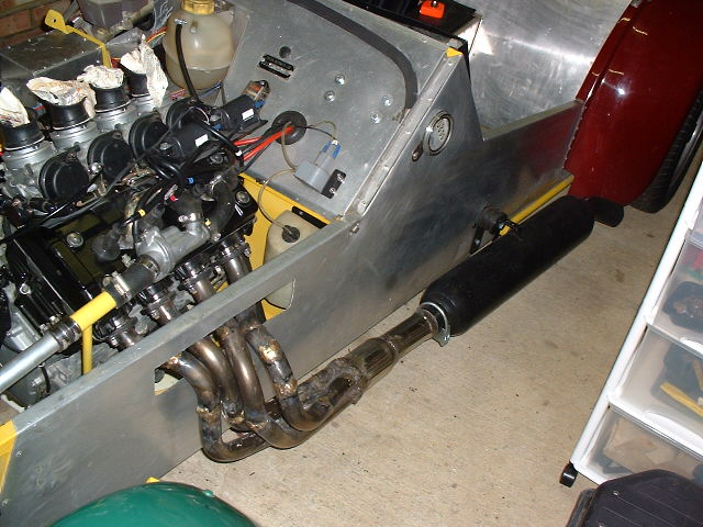
|
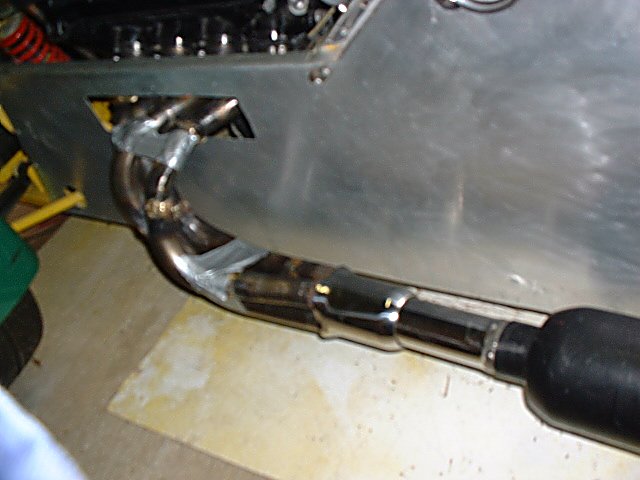
Finished Pipes on the car - side view |
 |
Finished Pipes on the car - top view |
 |
Finished Pipes on the car - Side view Far |
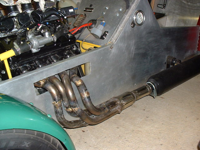 |
Finished Pipes on the car - Side view Close |
Now then fun bit. Put the pipes on the engine and tighten all the bolts. The fit is not quite perfect but is close enough.
Then mount the silencer, slipping the secondary stubby pipe into it. Tighten mount and U-Clamp.
Start the engine......
Mine was hesitant to start and threw lots of fuel out of a carb - a sticking float-chamber needle-valve seemed to be the problem. Fixed this by cleaning it all up.
The engine started - at 6000RPM!!!! Whoops - better set the idle speed a bit better!
The exhaust was smoking as I expected and things started to "set".
![]() May 2001
May 2001
The car engine must be used to fully cure the sealants. You can then clean the pipes up and paint them.
The engine ran fine with the pipes and there were no apparent leaks! Lots of fumes and smoke from the sealant and dirt from the pipes but that seemed ok.
After this I took the pipes off and painted them with the same paint to match the silencer. You can see the pipes are kind of lumpy but they do look a lot better than they did!

|
Finished Pipes on the car after painting in high-temperature Eggshell paint (as used on the exhaust silencer) |

|
After curing the paint has blistered in the places I put it on too heavily! |
I was "forced" into building my own as I live in an area with no car tinkers and no bespoke manifold makers. To get one professionally made would entail the hire of two car-transporters (there and back) and of course the pipes themselves. Around £800 in total. The raw ingredients of this cost about £90 (mainly MIG wire/Gas).
However the pipes are really not too good to look at and I have no idea if they will perform. I now think of the pipes as more of a "get me to a pro-builder" than a final solution.
The bottom line is unless you can weld like a demon don't bother. It has taken 3months on and off. Quite an achievement personally, and many lessons learnt. Would I do it again? No.