Marcs Conversion - The main bit
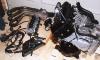 |
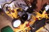
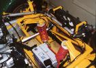
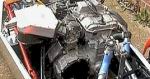
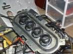
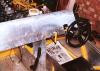
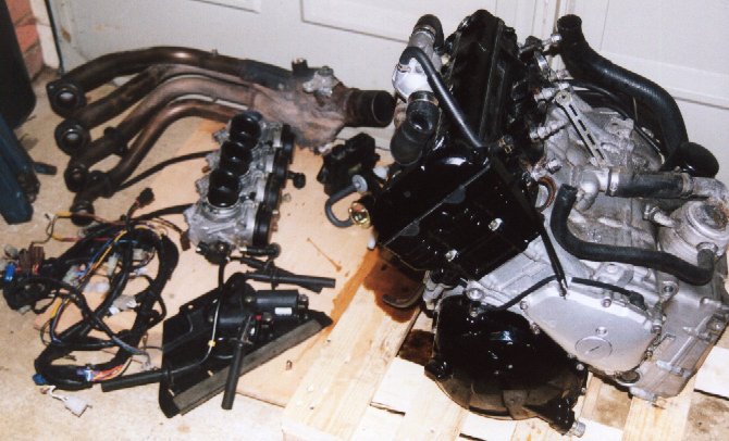
Here is the first package I received.
From top left to bottom right you can see:
Exhaust manifold, CDi unit, Fuel Pump, Engine, wiring loom, carbs and coil-packs |
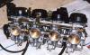 |
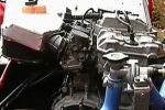
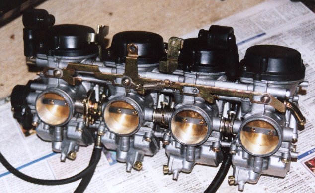
Yamahe R1 Carbs - Mikuni 40mm.
More like an SU than a Weber. Overall weight for these 4 is just 2.8Kg |
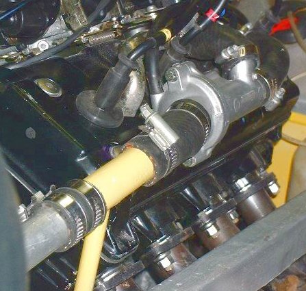
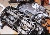 |
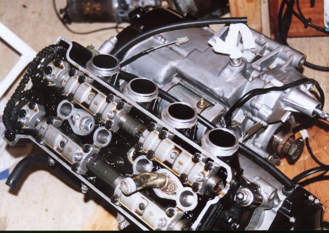
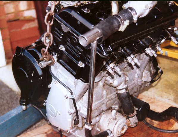
R1 Head Detail - See the chain driven DOHC. 5 valves per cylinder. |
Engine Mounts
I elected to make my own engine mounts. I scanned the pictures of the other cars
and compared the solutions. The general method is either to build mounts UP from
the floor level or build mounts DOWN from additional cross brace bars welded onto the
chassis.
I elected to do the former and basically followed the lead from the Fisher
Fury-Blade.
My mounts are rather agricultural looking but look good and strong. After
talking to Mark Fisher I elected to soft mount my engine with rubbers. I bought
three large cortina round bobbins and used these. My mounts are made from 3mm angle
and 16SWG box mild-steel. They are MIG welded together. Due to the long bolts
used in the bike engine I also welded spacers onto the mounts to allow full bolt grip into
the block.
 |
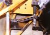
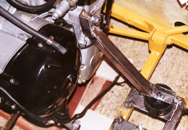
This is the front
mount. See the newly welded plates on the chassis of the car. |
 |
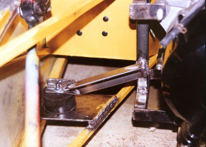
This is the offside mount viewed from the front of the car. More
support weld plates on the car chassis as my Striker had an
"old-style" set of Ford-only mounts. |
 |
Here is the rear mount. (Chassis rail visible is the nearside top rail). |
 |
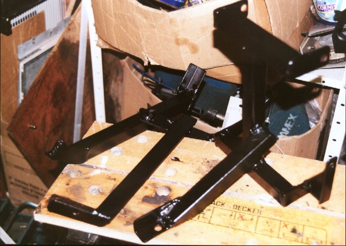
The three engine mounts after painting black.
|
 |
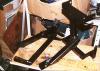
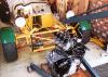
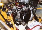
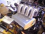
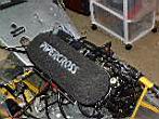
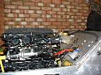
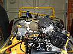
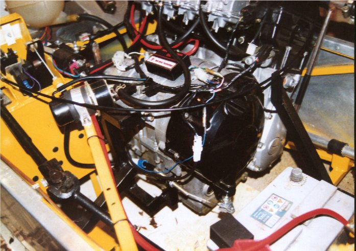
Here is the engine trial-fitted into the car on the mounts. See the wooden boards on bricks underneath. These were set at a height of 4" to set the basic engine ground clearance. |
 |
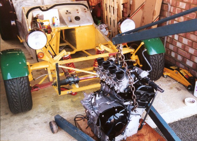
Engine on crane (a big lad is more use - it only weighs 70Kg!!!). |
The three mounts suspend the engine about 4" off the ground so as to be inline
with the bottom chassis rail. The location of the engine is such that:
- The prop is approximately inline with the diff flange (no more than 5 degrees).
- It doesn't hang out over the nearside rail. R1's have an infuriating thermostat
there!!!! Grh!!
- It allows access to the rear of the engine for positioning the prop/flange
and alternator repair.
- It is not too high so that its CofG is good and a small (2") bonnet scoop will be
enough for airflow.
Does it work?
The only tests so far have been performed by me jumping up and down on top of the engine
in the engine bay. The engine does not move appreciably and none of the mounts are
stressed. Previous to this all welded joints are tested by whacking them with a big
hammer over and over!
Battery location
Due to me originally intending to use an electric reverse I elected to keep
the car battery rather than use a small bike battery. To improve layout,
maintenance and CofG I mounted this low-down at the front of the engine
bay. To do this easily (and provide an easy plate location for the the
engine mounts) I welded in a new crossbrace at the front. The
battery is held down with some bolts and clamps. It allows easy
maintenance and charging without removing bolts etc.
|
 Feb
2001 Feb
2001
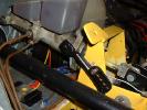
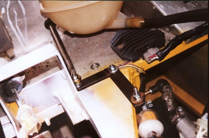
Battery Location and clamps. See the newly welded-in
crossbrace at the rear of the battery.
You can also see the front engine mount arm quite clearly. The
crossbrace allows both the battery "shelf" and the engine mount.
|
I made up all new battery leads to take the battery volts and earth into the cockpit.
Feb
2001 The cheapest place to get the cable is from Vehicle Wiring Products.
Multi-part connectors are cheapest from CPC.
The only problem I can for-see with the arrangement is if the bike
alternator/regulator does not produce enough charging current to keep the
battery full. Watch this space for news on this.
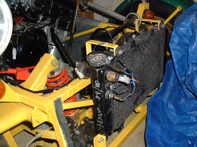
Radiator & cooling system
I used a bike radiator (from an FZR1000 bike). This has only an IN and an OUT on
it. The R1 has no less than 5 cooling tubes.
I elected to plumb the engine in as follows.
| R1 Pipe (direction from engine) |
Plumbing |
| Main Top Outlet (OUT) |
Into Radiator Top |
| Main Bottom Inlet (IN) |
Into Radiator Bottom |
| Oil cooler outlet (OUT) |
Combined with radiator top hose |
| Bottom Breather hose (OUT) |
Into header tank at bottom |
| Top thermostat out (OUT) |
Into top of header tank |
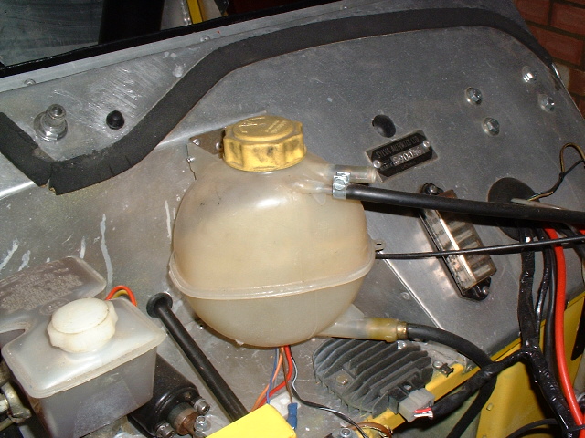
I located the radiator on new brackets (3mm plates welded to chassis) at the front of
the car. I then bought some extra 25mm bore radiator bends from a local car shop and some
1" Alluminium pipe to extend the pipes. A total of 4 pipes Ali pipes were used
and the bike radiator hoses were cut to form some of the bends. I used an Astra Mk2
header tank as it was cheap (£5) and relatively small. Bike header tanks are no use
as they are really just an overflow (one outlet) type only. The tank was
mounted on
a small bracket to the firewall.
April
2001 There are no
water leaks etc (yet).
The Clutch May
2001
You can re-use the car engine cable. Simply weld-on a bracket to something solid
(i.e. an engine mount) near the clutch release arm. The clutch release arm is
usually just held on with a circlip so it can be rotated as required.
Shorten the cable to suit, making sure that the adjuster nut will be about
half-way down the bracket to allow for tensioning. Make sure you leave
enough slack cable to accommodate the slight variations in engine position.
Feb
2001
Top Tip - You will need a much shorter cable than your old car one.
Buy a cable from a motor-factors (Mk3 escort for me) and cut it down to
size. Make sure it has the right end to go into the pedal box (both the
plastic seat and the metal pin hole). Cut the cable at the nipple end down
to size. Aim to have the adjuster approximately half way adjusted
when the arm is met. Now you have the approximate position take the cable
off and fix on a new end. Some people say you can get special crimp ends -
I couldn't find any so I took a shortcut. Get a small nut (M3) and put
this onto the end of the cable so that the end pokes out about 1mm. Then
secure the two together and use the trusty MIG welder to weld the nut to the end
of the steel cable. Clean up the weld afterwards and you end up with a
strong small end suitable for use with the bikes clutch arm.
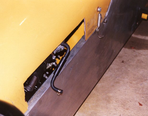
|
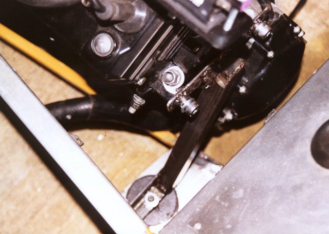
Feb
2001
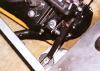
Clutch Cable mount details.
Picture is a bit blurry I'm afraid. The clutch cable mount is welded
onto the engine mount. You can just see the adjusting nut of the
cable. The engine clutch arm has been rotated so that it is roughly
inline with the cable mount. |
The clutch release arm on a bike moves about 1" very easily (this is just slack)
and will then be hard to move for another inch or so. This is the ACTUAL arm motion
of engaging the clutch.
May
2001
I expected the clutch to be an easy job. Already connected I thought it
would just work. However when I fitted the propshafts and tried it out it
stuck wide open as I tried to release the clutch. I dismantled the clutch
to try to work out why.

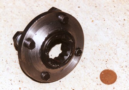
|
1 Clutch spring plate retainer
2 Clutch spring plate
3 Clutch spring plate seat
4 Pressure plate
5 Pull rod
6 Friction plates 7off (Inside diameter = 124 mm)
7 Clutch plates 6off
8 Lock washer
9 Wire circlip
10 Clutch plate
|
11 Friction plate (Inside diameter = 135 mm)
12 Clutch damper spring
13 Clutch damper spring seat
14 Clutch boss
15 Thrust washer
16 Clutch housing
17 Bearing
18 Starter clutch gear
19 Bearing
20 Starter clutch assembly
21 Circlip
22 Starter clutch idle gear |
After the whole thing was taken apart and checked I now had a pretty good
idea of how it fits together. I put it back together and tried it again.
Nope - still stuck wide open when I tried to release it. At least it
had now stuck open in the failure mode, which enabled me to see what was
wrong. As Cam and me had discussed we thought it was the clutch boss
somehow being pulled out so far it was un-latching itself from the basket.
Basically there are a set of mortice-and-tenon type joints where the two pieces
interlock. However if you pull too hard on the lever when the engine is
running it seems to jump out of position and wedges the clutch wide open!
In this state you can turn the bit at the front by hand - which you can't do
when it is engaged. The symptoms were confirmed when I turned one of the
bolts to undo the thing - it pinged the spring back into position and the clutch
was engaged again.
Fixes? Perhaps the clutch pedal is pulling the lever too far and
pulling the thing out? Perhaps the spring is weak? It's difficult to
know as all the components look fine.
A bit concerning from a USA website: The R1 was recalled before it got out of the factory gates for
attention to its clutch. Then it was recalled again for attention to
its clutch. Some had blown up in intense situations. This does
not apply I am told to UK engines.
Time passes... Thorin sits down and starts singing about Gold.....
After some thought I realised the only that could be happening is that the
arm is pulling the clutch too far. I measure the linear throw of the cars
pedal at the point it interacts with the clutch. Mmm... 30mm. Seems
a lot. I then measured some bikes at work. Mmm... 10 to 15mm.
Aha!
With this discovery I elected to measure the R1 clutch throw.

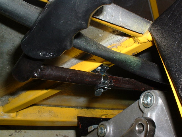
|
Measuring the clutch throw. Use a piece
of tape and mark a centre line on the tape and the arm.
Use a long stick to poke down the pedal box which allows the clutch
pedal to be moved. I used an offcut of steel 1/2" bar I
had. This allowed easy exercising of the clutch with visibility of
the arm.
Aha! Theres a resistance that is constant up to a certain point -
and then becomes very soft. I bet this is the bit that you don't
need to pull!
Measurements showed the throw required to be about 15mm. Half of
the clutch throw.
I started the engine and repeated the experiment by just pulling the
clutch back slightly. Yep - the clutch then turns drive on and off
and doesn't jump! |

|
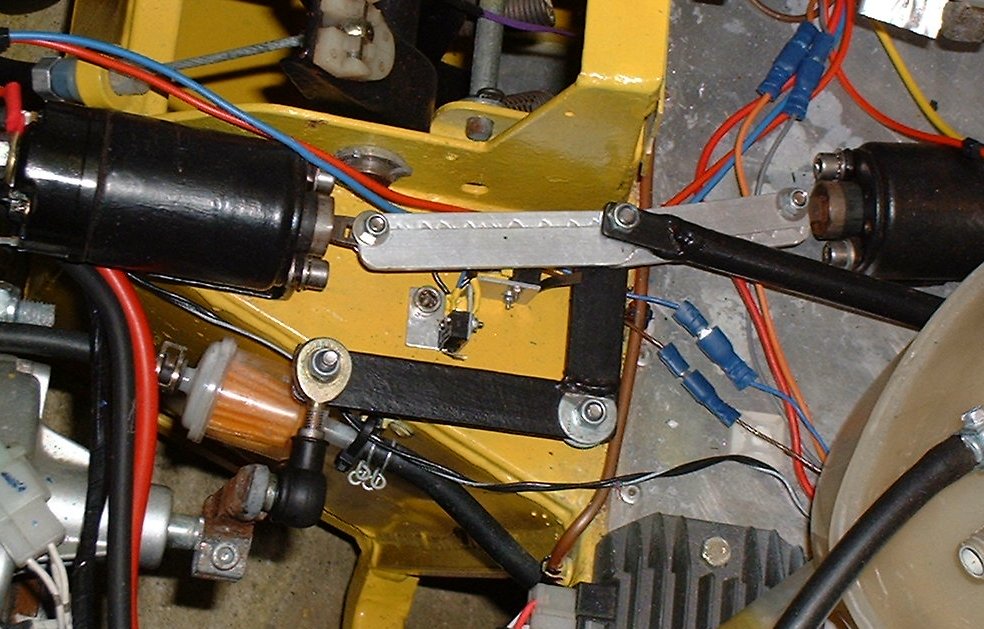
With this in mind I opted to limit the clutch
pedal travel. There are loads of ways to do it but I wanted a simple
method that could be adjusted. I did this by making an end-stop from
a 6mm bolt (40mm long I think), welded to a 1/2" pipe again 40mm
long. A hole was drilled in the pedal-box and two nuts at each side
used to adjust the position. The pedal stop hits the top of the
plastic moulding in the pedal. |
I then tested this.... Yep! fixed. The prop can be seen rotating
and stopping as the clutch is used!
This resulted in the first moving test of the car (30th May 2001). It
moved so nicely too ;-)
Throttle Cable
Try to get the cable from the bike. It will probably be too short but its
fittings may be useful. A great tip for sources of cable etc is a bike shop
(pushbike). You can buy cables very cheap and they often sell the bits to make your
own too!! I was quoted £16 from SpeedyCables for a new cable with fittings.
By reusing the old fittings (from the xflow installation) and buying a new cable I did the
job for £4. Bike throttles use two cables, one to open the throttle and one to shut
the throttle. For a car installation just use the opening one and make sure you
route the cable as cleanly as possible. Any bends/kinks will show up as problems in
closing the throttle fully.
Note that the range of cable movement is very small (only about 15mm). On the end
of the accelerator pedal this equates to about 25mm of travel from idleRPM to 14kRPM!!!
With this in mind I welded on a new link plate onto the accelerator pedal arm and
relocated the holder too. This gave me "proper" 4" travel.
Feb 2001
I am still not 100% happy with the
throttle cable linkage. The pedal now sits "higher" that the
others in the rest state. A re-weld of the bracket may be required.
This is something that can be done later however.
|
Extra plate on pedal and new holder (both MIG welded) |
Choke Cable
Again, try to get the cable from the bike. It will probably be too short but its
fittings may be useful.
A replacement cable can be bought from a car-shop for £4 or so. The bike choke
plates are sprung so make sure you get a choke cable that has a built in
"twist-lock". The first one I bought didn't. So
technically it cost me £8! Doh!
You then just secure this cable to the dash. Try to route the cable as
straight as possible. You will have to clamp the carb-end of the cable
onto a handy carb screw/bracket.
Other brackets
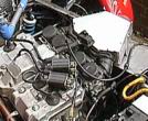
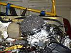
Coil Packs
The coil packs need locating. On a bike they are suspended upside-down on a
plastic plate. I elected to mount them on a small steel plate above the head so as
to keep the same HT leads. This keeps them away from the hot exhaust area and allows
them to move slightly to allow for engine vibration. I mounted my packs on
rubber foam strips on top of the plate. Nylock Nuts were welded underneath
the plate and some long coach bolts used to bolt the packs onto the plate.
The foam will have cushion vibrations.
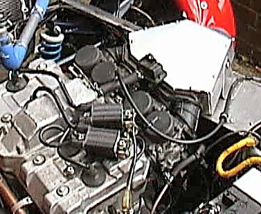
The bracket also provides the clamp for the choke cable.
|
Feb
2001
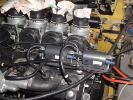
Coil Packs and choke-cable bracket.
Carb's have paper jammed in to prevent crud getting into them.
|
Electrics
Loom
You can use a standard bike loom virtually untouched. To keep things neat I
elected to hack up the loom and remove all lighting, fuses and superfluous relay-crap.
I then laid the loom back over the engine and re-taped the loom to fit as required.
I added a multi-plug to take this loom into the cockpit area. It
meets the other looms (front engine bay, rear of car and dashboard here).
CDi
I put the CDi unit in the cockpit on top of the transmission tunnel on some foam tape
(with bolts). This keeps the unit dry and cool relative to the hot engine bay.
The tape helps protect against vibration.
Starter Relay
Bike starter motors use a relay rather than a solenoid (ok - the basic principles are
the same but the physical scale is different here). I mounted mine on the
transmission tunnel using its rubber boot holder in a homemade (welded) frame. I
also mounted the rubber-clipped relay unit here too.
Fuelling
I am using the bike electric fuel pump. I removed the weird rubber bracket on it
and mounted this on a chassis crossbrace with a small Ali clamp and some more foam tape.
This will protect against vibration. Hopefully the pump will be man-enough to
pull from a tank 5feet away. If not I have the old electric fuel pump and regulator
from the XFlow setup.
I used a cheap disposable filter from the tank and re-used the bike rubber petrol
hoses.
Airbox/Filters
TTS engineering claim expertise in bike engines in cars as they have been doing
hillclimb cars for years. Their opinion is that you can re-jet the carb's to suit
either airboxes or foam-filter setups. There is some contention on this point it
must be said.
My intention WAS to have a homemade 2part airbox. The bottom part of the airbox
will be bolted around the necks of the carb inlets, and will house the air filter unit at
one end (probably at the windscreen end to take advantage of the clean high-pressure air
there). The other part of the airbox will be moulded into the bonnet such that when
it is closed rubbers will seal the airbox.
April
2001
Scrub that idea as too complex. I don't want holes and to reduce the
effects of carb re-jetting I opted to make my own full airbox.
|
Inspiration.
Steve's CBR1000 Striker with a homemade airbox for Jeremy Philips at
Sylva.
This one uses the original airbox pipework and an "old K&N
I had lying around" said Jeremy.
Mine will be fabricated from household plastic things instead (very
Blue Peter!)
|
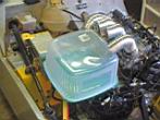
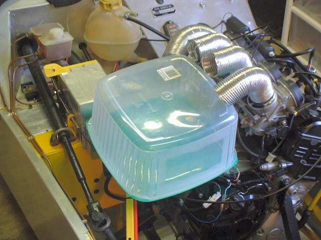
After lots of excellent discussions on the bike-engined cars Yahoo-Group I decided to try the homemade airbox before resorting to foam filters.
I got hold of some flexi tubing just big enough to go over each carb (2" in my case). I then looked for some household objects to use as an airbox.
A chap on the list reckoned the rule-of-thumb was 10x the engine capacity. So for my 998cc we are looking around 10litres.
Mmm... My first candidate was only 5litres. A storage box from the kitchen was 10litres. My God... it's huge!
It didn't fit too well in the Striker engine bay and looked utterly naff too. I would need even longer duct pipes and I wasn't too happy with them anyway - I couldn't tighten the tye-wraps tight enough so they kept falling off the carbs.
|
Two big household containers and duct pipes to them. The 5 litre one looks ok for fit but would probably be too small for a 1litre engine. The 10litre one just looks daft!
|
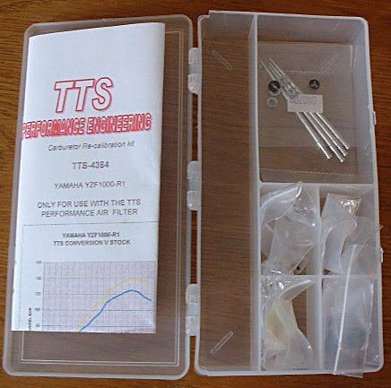
With this in mind I have decided to take the easy option and buy a foam filter from Burton (£34 for PiperCross PX600), make my own backplate from an Ali sheet, and buy a rejet kit from TTS. Job done.
|
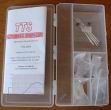
The TTS jetting kit for an R1 for car use with a foam filter. Not much for £90. Just some new needles, main jets and some epoxy to seal some holes. The instructions are pants but TTS are very helpful on the phone.
|
|
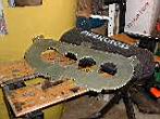
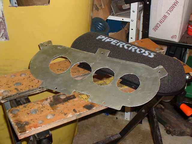
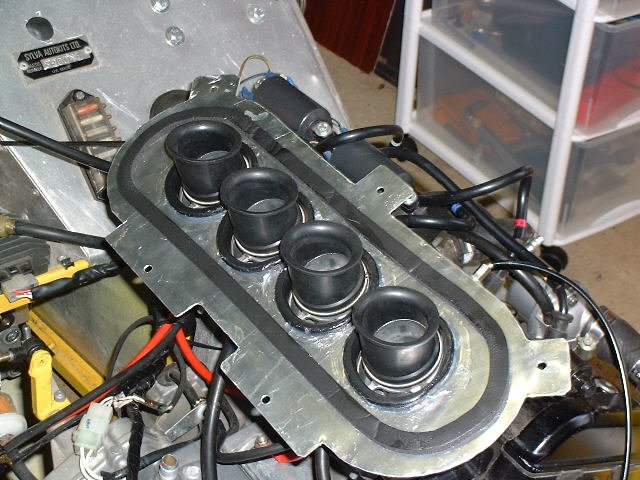
Using a piece of 18SWG Aluminium I had lying around I made a plate for the filters.
The plate attaches to the carbs via rubber pieces. These hold the airbox onto the carbs on the bike. I had to buy mine and they were £9.60 from a Yamaha dealer.
The completed plate is shown alongside the filter.
The bottom picture shows the reverse side with the carb rubbers
installed.
|
|
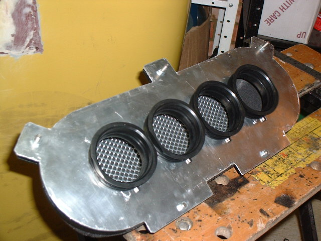
The plates you buy are made such that the plate fits inside the filter base. This provides the optimum seal. My plate was a little too big so I used some foam tape around the inside to seal the filter onto the plate. You can also see that I have secured the gaps in the carb rubbers and plate with bathroom silicon sealant.
|
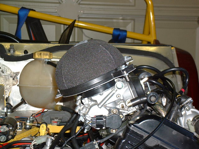
|
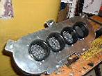
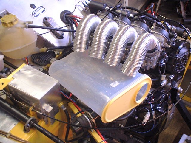
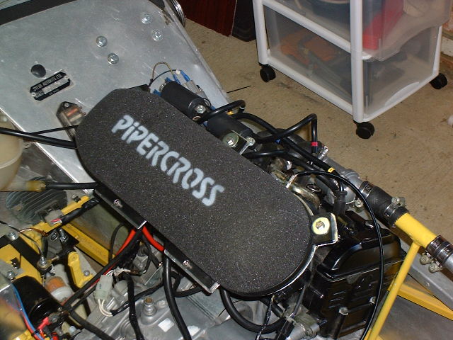
The completed filter assembly on the carbs.
As I made my own baseplate I did not have the female sockets for the DSuz
fasteners. So I removed them and used good ole 6mm bolts instead.
|
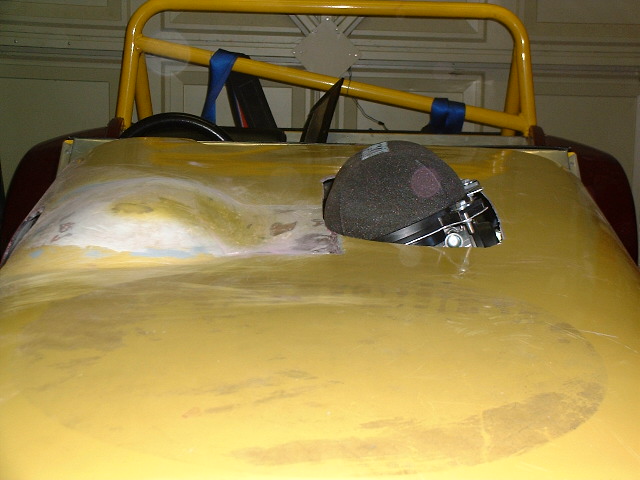
|
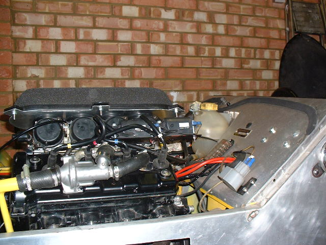
The filter assembly from different angles.
|
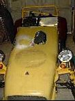
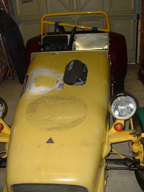
Bonnet Line
The engine is too tall for the standard old bonnet. The new bonnet only gives
1" more engine space so I elected to modify my old bonnet by adding my own homemade
GRP scoop.
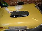
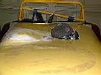
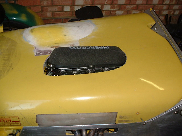
|
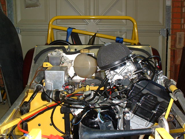
The next stage was to hack the bonnet around to get the carbs and filter
clear.
As you can see they stick out quite a long way (up to 3" maximum).
It is unlikely that I will be able to buy a new bonnet from Sylva with this
level of clearance, so I will require a bulge.
The bonnet is a state and will need a fair bit of work to get it ok.
See further into the page in the Bodywork section for details.
|
Oil Pressure/Sumps etc
General consensus in the kitcar world is that small engines (1litre or less) do not
need any modifications for good oil pickup on the road. For track use baffling or
dry sumping is the way to go. This is said to be required for larger
engines such as Blackbirds/Hayabusas.
Exhaust System
NEW!  NEW!
NEW!
A big section - so it has it's own page: Making your own Exhaust Manifold!!
Carburetion
Bike carburetors look more like SU types than Webers. Their operation
is certainly similar to SUs. Due to the modified engine loads/air-intake
and exhaust from the bike expect to have the carb's re-jetted (Dynojet kit
etc). TTS have a rolling road and experience of re-jetting bike carb's for
cars.
Gearchange
I first elected to use the homebrewed system of electronic change from the steering
wheel. Button changes are soooo coool. But then I got scared of being stranded
somewhere with no gears if my circuit broke. It is also a very tight fit to mount
control solenoids down under the gearchange arm as you are very near both the propshaft
and the car side panel.
With this in mind it is easier to move the control solenoids up to the battery shelf
area. Once this is done you are at the correct level for a manual linkage. To
implement this I used a steel tube coming in from the dashboard and a bellcrank pivot to
turn the for-aft motion 90degrees as required of the gearchange arm. I used 6mm
rod-ends to translate motion.
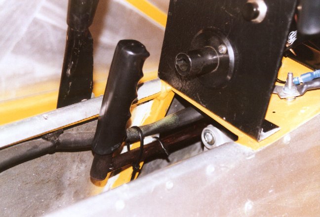
The rod comes through the bulkhead just under the dashboard. I have welded a
handle onto the rod and used a rubber grip from a pushbike to finish it off. The rod
needs quite a strong push/pull as it only moves about 15mm either way.
Once the system is proven to work on the road the solenoid shifter system can be
activated. It is designed and built-onto the car and works with the
vehicle stationary. However bike-boxes are rather more notchy than car
boxes so changes may be required later.
Reverse
I originally intended to have an electric reverse. This was due to cost
limitations as proper reverse boxes cost £520+. I was to put a cog onto the front
section of propshaft and mount a pre-engaged car starter motor on a bracket adjacent.
When reverse is required you simply press one button to engage the two cogs and
then use Another control to activate the motor. The main problems with this are:
- No reputable prop manufacturer wants to weld a cog onto the prop. The reasons
cited are reduced strength due to weld, the thin guage material is not meant to take
lateral loads in its middle, and difficulty in balancing.
- Controlling a car starter motor to get a proportional control (i.e. not just on or off)
is difficult to say the least. Your electronics must be capable of withstanding
stall currents of over 300Amps. The switch devices must be kept cool so large
heat-sinking is required.
- Car starter motors are not intended for continuous use - they get hot and burn out.
- Even the largest car starter motors only have around 1.2HP. If you do the sums to
see what kind of slope you will be able to reverse-up you will be disappointed.
Even
a steep kerb (unless you have a run-up) is tricky.
With these in mind I had to plump up for a reverser box. :-(
Prop Drive Plate
To take drive from the engine gearbox output to the prop you need a drive-plate.
This can be made from a bike sprocket cut down and welded to a support plate.
This is then machined and balanced. This can be done for you by Fisher
Sportscars et al for around £70.
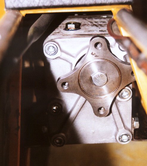
 |
Prop Drive Plate made from a bike front-cog welded to a backing plate. Welded, machined and balanced. |
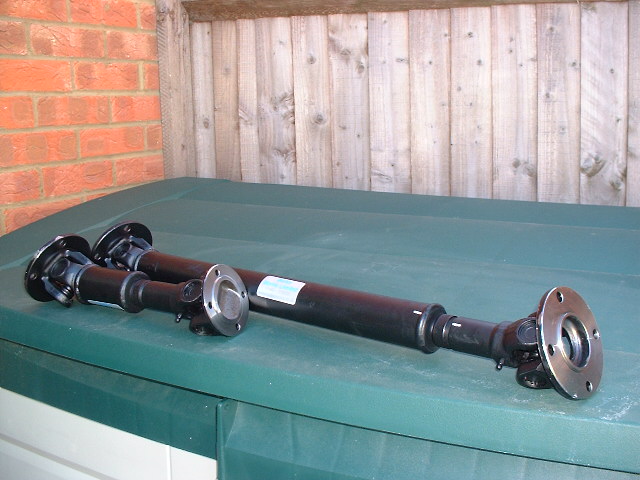
Propshafts
May 2001
You will need new propshaft(s). Due to the extra distance from the engine to the
Diff you need a split prop. If you are putting a reverser box in then you have two
seperate props. The front one is conventional fixed length, whilst the rear has a
sliding joint to allow for Diff fore-aft movement.
If you are not having reverse (competition car only) you can just have a two piece with
a central support bearing. This sits where the old gearbox mount used to in your
tunnel.
Both solutions cost from around £130 per pair to about £500 per pair
depending upon who you speak to. My Bailey-Morris set was £164.
Make sure your prop is balanced properly! There has already been one case of a
car with an incorrectly balanced prop. He noticed vibrations but continued to use
it. What happened? The prop snapped at the gearbox UJ and ripped half the
engine apart (and lots of other bits). He was lucky not to be injured.
Dashboard/Instruments
A new dashboard was designed and built to accommodate the different
instruments.
Laying out an "ergonomic" dash can be done quite easily.
Attach a long piece of cardboard over your dash as a drawing sheet. Sit
normally in the car, armed with a felt-tip pen. as you sit mark out the
areas of the dash you can see with the pen. There will be some which are
obscured due to the wheel etc. Once done take off the card and you should
have a clear set of areas for placing instruments.
A new revcounter was obtained (Burton were the cheapest - an Eliot Clubman
that goes to 14kRPM). My steering-wheel mounted button shift has a gear
display too that tells you which gear you are in!
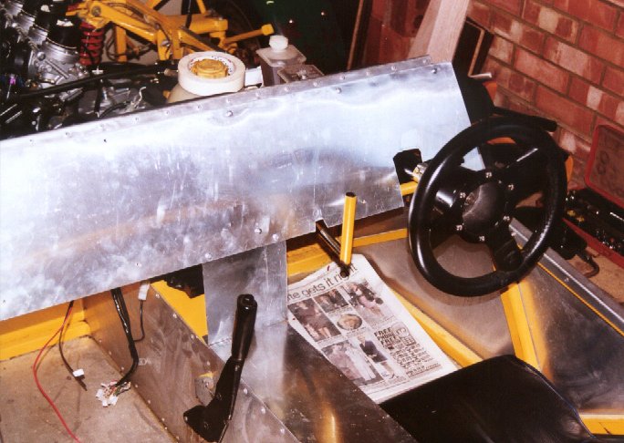
 |
New dashboard shape fitted to car. It's made of 18SWG Ali.
Notice the manual gearchange handle next to the wheel. |
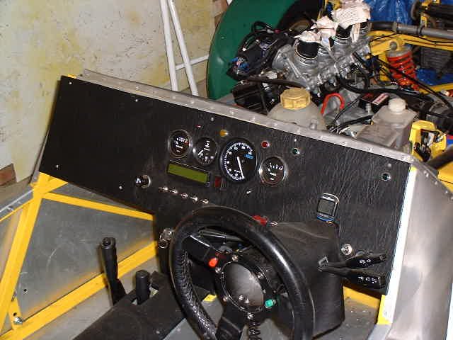
|
Feb
2001
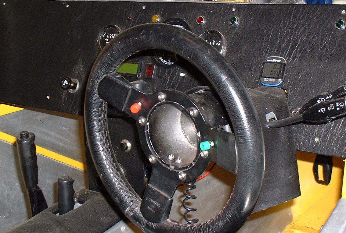
Finished Dashboard - see new Revcounter and 7segment LED
display for gear. See the manual gearchange arm just to the left of
the steering wheel.
Speedo is pushbike computer.
Other instruments are homemade. LCD is a lap-timer, a shift-light
is also fitted.
|
|
Feb
2001
Rear of dash showing multi-plug wiring. Still more of
a mess than I'd have liked but not too bad. It can be removed in a
few minutes as most connections are via multi-plugs into looms.
The wiring at the bottom left is the tunnel-top. This has the ECU
and fusebox amongst other things!
|

|
June
2001
Completed dashboard with the tunnel cover in place.
Some of the switches/lights are not in too good a spot so I will redo
the dash later.
|


