So now the car is road legal I am having some fun with it. There are lots
of things to improve on - kitcars are never "finished"!
The pedal was sitting slightly proud of the other pedals and this was making coming-off-the-throttle quickly awkward. I decided to re-visit this and was shocked at how easy the solution was. All I had to do was chop the end piece off the arm that the old XFlow setup used. The pedal will now swing freely and the adjuster nuts can be used to set the position of the pedal with respect to the other pedals!

|
Chopped off end allows the arm to swing fully!
Doh! |
I am looking to enter the 750MC racing series next year and am concentrating on getting t he car sorted for that. The first area to turn to is the gearchange. My original plan was push button gearchange. In practise I have found the solenoids are unfortunately not 100% reliable in their changing. Sometimes the gear goes in, while others it refuses. As the 750MC rules forbid these sort of changers I decided to stop work on this one for now.
The manual change I made was only a temporary/emergency measure, designed for finding neutral and for backup. I have found the straight-push arm approach to be awkward, with the lever too close to the dash and not easy to put force on. It is also the "wrong way around" when compared to rally and touring cars which use pullback for UP, and Push for DOWN. This allows the natural momentum of the car and driver to help rather than hinder the change.
So I decided to modify the gearchange to improve its action and position.
 |
The bellcrank was re-used, just being turned over.
This allows the rods "push" to move the gearchange the opposite
way.
|

|
This shows the bracket for the main lever. It is a small steel bracket. I cut away some of the Ali wrap-around under the tunnel cover and took the paint off. I then drilled a hole in the bracket and put it in place. I then welded the middle of the hole to join the two. I also welded the brackets edges too. The lever then pivots on this and pushes the actuator rod that goes through the dash to the bellcrank. |

|
The completed bellcrank with the header tank back in place (and no, they don't interact!). You can now see the new pushrod in position.. |

 |
Completed lever system. The feel that this gives is far superior to the old system and the rocking action is more natural for your arm to perform. The handle position is now perfect too! |
![]() September 2001
September 2001
Driving Report:
Big Improvement. Big improvement. Oh yes.
The action is light and sharp with virtually no slop in the linkage. I
prefer the conventional direction of push for Downs and pull for Ups too.
It feels more natural somehow. Combined with the improved throttle pedal
position I can clutchless up-shift without error all the time. The
gearchange is lightning fast!
Fuelling
The engine will only rev to 9000RPM in top gear. It is also rather
laborious at the higher revs in lower gears. Flat out in top is only
104mph. I suspect either fuelling or my dodgy exhaust!
I tried going to bigger main jets (150's versus 144's) and there was no improvement. Everything seems to point to the exhaust. All the filler has now burnt out so it is blowing and obviously causing lots of back-pressure. I need to visit Tony Law in Leeds to get one made - but the logistics of getting the car there are quite tricky for me as I don't have a tow car.
Further details: TBA
![]() September 2001
September 2001
Even with the fan permanently on the engine runs at 100degC. OK
you might think - and yes, it is. But in traffic or at standstill even at
idle the thing will overheat. It will get to 120degC and the header tank
will begin to overflow. Not good.
I checked all the pipes and re-checked the way I'd plumbed it - no problems as far as I can see so we must need more radiator surface area to get the temperature down.
With this in mind I visited the local scrapyard and had a look around. I took the Striker which helps as you can check things will fit, and more importantly - it gets the guys interested and helpful. I settled on a Renault 11 Ali/Plastic radiator for £18. It is the same width as the bike one but about 75% taller. Once I had got the huge fan off it was pretty light too. I manually straightened out the few fins that were bent, and I cleaned it up with a pressure washer. I used this to flush the rad too - lots of orange water came out as expected.

|
The old rad on the car and the new Renault rad next to it. Checkout the giant fan on the floor too! |
The problem now is how to best mount it with minimal bracket manufacture, and how to plumb it in. The R1 uses 25mm pipework and the rad is 32mm so I have to do some bore reductions.
For the brackets I used the existing top brackets bent back to fit the new radiator into the nosecone. Once the top was located in the nose I made a simply 'U' shaped Ali bracket to hold the radiator to the bottom chassis rail. I tapped an M6 hole in the chassis for this.
For the pipework I got some flexi pipe in 32mm bore. I cut this 1/2m length into two to make the two pipes I needed. The obvious orientation was to put the radiator this way around as it kept the wiring loom in the same place and the top pipe the same. I used an offcut of Ali tube for the new bottom pipe.
The radiator has no temperature sensor so I had to work out how to mount the sensor from the old (bike) rad. The plasic end-caps of the radiator are pretty substantial, particularly around the temperature switch area where it has some extra thickness. I opted to drill a hole in this and use the temperature sensor to tap its own thread. I was a little sceptical as to whether it would work - but it doesn't leak and tells the temperature ok! When doing this make sure you use a fast drill speed so that the plastic swarf comes off in nice big long strands OUTSIDE of the radiator.


|
Closeup of the hose outlets and the temperature sensor (RH picture). |

|
Top brackets and filler-cap detail. You can just see the header tank outlet behind the filler cap. I was not using that so I blocked it off with a shirt piece of hose, a bolt in its end, and two jubilee clips. |

|
Top brackets with extra small Ali brackets. This saved me having to make new chassis mounts. The top hose is 32mm flexi and goes straight onto the radiator (32mm) outlet at one end, and the 25mm Ali pipe at the other end. |

|
Completed radiator in place. The chicken-wire on the front is to protect the fins against accidental damage. |
Testing:
So far so good. The engine has been up to full running temperature in
the garage (rain stopped real play). No coolant leaks and it appears to
now run at a pretty constant 90degC. Overall cost of the upgrade has been
£30. (£18 Rad, £10 pipe, £2 jubilee clips)
While trying to balance the carbs I have found that without the fan turned on it will still overheat :-(
Whether this is to be expected I don't know.
In case someone is interested I have uploaded the Yamaha drawings of the plumbing in the bike,
and a sketch of how my pipes are routed. Does anyone think I have the connections wrong?
![]() April 2002
April 2002
After some on road tests its obviosu that the problem is still there. i.e. it overheats (or gets near to) when it is coming down after a run.
I decided to look through some books and see what is wrong. It didn't take too long to work out that the main problem.
I have a vented expansion tank, AND a vented radiator. There is no pressurisation of the system!
A look at some drawings from the books will show this:
To get the system pressurised I will have to do one of two things:
1 - Use the larger car radiator - which has an overflow pipe to a pressurised header tank (that I will have to buy)
or
2 - Use the bike radiator again - which has a pressure relieved expansion outlet which is unfortunately snapped off :-(
In both cases I would have to adapt the hoses/pipes to allow all the Yamahas 5 pipes into the radiator. I can then use whichever expansion pipe is available to
a tank.
I actually have 3 radiators. I got the first one with the engine package, but I deemed it unsuitable.
| TOP LEFT: The original rad I received. Pro's: all 4 inlet/outlets, pressurised type with header outlet intact Con's: Main inlet/outlet is a bit small, No temperature sensor, completely different mounts to my existing ones |
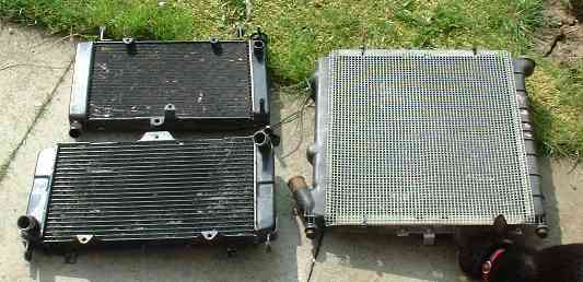 |
RIGHT: Car Radiator Pro's: OK mounts, main in/outlets ok size, thermal sensor Con's: Non pressurised type (need new header tank), only main in/outlets, heavier when full |
| BOTTOM LEFT: The replacement. Pro's: Right mounts, right pipes, pressurised header out (but also a con as it's bust!), right pipe sizes, thermal sensor Con's: Only main in/outlets, bit rough (fins) |
|
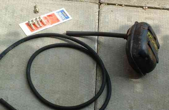
After some thought I decided to stay with the car radiator, add some extra in/outlets and find a pressurised header tank with just the one outlet. I got some hose, some adapters and the all important pressurised header tank. I am most proud of this last item. It is made of steel (not this namby pamby plastic rubbish) and was originally fitted to an Austin Princess, a car that ranks in my all time most hated cars list; along with Volvo 340s, Morris Minors, 2CVs, and anything by Skoda/Lada. But I digress. |
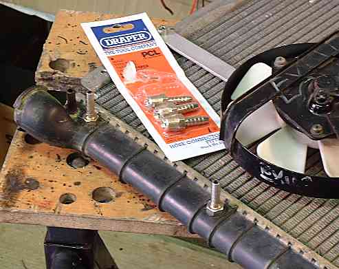
| The extra inlets / outlets are 1/8th BSP to 1/4" adapters meant for air lines etc. I got these from the local farm machinery shop (people in cities will need to go elsewhere!).
After looking over the R1 manual I tried to plumb the hoses as close as I could. I was already combining two hoses (oil cooler outlet) and thermostat outlet with a T-piece I made at the start of the project. I had to add two extra connections. One was for the thermostat overflow, and the other for the overflow from the backside of the engine at the water pump inlet. To add the adapters I worked out the positions and then drilled some 11mm holes in the radiators plastic side tank. I then tapped with an M12 tap to get some "grip" for the thread. This didn't work so I used a stepped hole cutter to take 1/2 the hole out to 12mm. By gripping the adapter by mole-grips and brute force I managed to thread them in. I was gonna try araldite but it only works to 60degC apparently. |
|
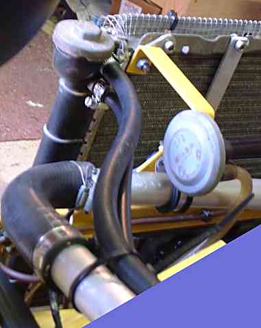 |
The radiator back in position with the three extra pipe connections in place. The very top pipe goes off to the new pressurised header tank. The next pipe is to the thermostat overflow, while the lower one (which you can't actually see) is to the back of the water pump. |
| I chose to mount the expansion tank roughly where the old (pointless) one was. This gave a "head" of water (even though I don't think that that is required), gave easy pipe routing, and most important of all - it was easy to mount. I opted just to make a strap from Alluminium strip and mount it to the bulkhead. It is held tight as there is foam padding front and rear which is compressed quite hard when the screws are tight. I also ran the overflow pipe down to the tunnel so that my feet wouldn't get hot and wet if it did overflow. |

|
After filling the system I ran the engine up, sorted a leaking pipe where I hadn't done the clip up tightly, and then let it come to running temperature.
It reached running temperature with all of the pipes warm.
Watch this space...
My homemade exhaust manifold looked really sick. It was leaking from the brazed joints (they had cracked) and was sapping power noticably. I had always intended to go up to Leeds to see Tony Law. However when I looked at the logistics of ghetting the car from Cambridgeshire up to Leeds, leaving it a week and then fetching it back it was horrible. The costs soons spiralled too as I'd have had to hire vans for transport two weekends running.
Speaking to my business partner [Custom AutoTech LTD] he mentioned a place over in Norfolk, near to Snetterton Race track. I called the place and decided that they (Competition Fabrications) could do the job. As it wasn't too far I thought of driving it, but decided on trying to borrow a trailer instead. Fortunately Alistair offered to trailer the car there and back with me! Cheers Bud!
A fellow kitcar builder (Richard Miles) is building a brand-new Striker R1 with all the shiny trick bits he can muster. He too wanted a manifold and as he is even nearer we did a joint deal.
Richard has a growing new website here.
The chap who runs Competition Fabrications is Nick Paravanni. It quickly became apparent that they were highly skilled metal workers, but were unable to recommend designs etc. Fortunately Richard is a thorough sort of chap and decided to do loads of reading up on the subject. He obtained measurements from various sources, studied books and the web and came up with a design that looked like a winner. I hold zero responsibility for this design - it's all down to Richard! Cheers Bud!
The exhaust is made of stainless steel and is a 4-2-1 design. Exact details of the manifold can be found on Richards site. Let's just say it is of tuned length and designed to give multiple gaseous reinforcements throughout the rev-range :-)


The quality of the workmanship is outstanding. The tubes are bent in the "old fashioned" way using heat and experience. Consequently the tubes are all of constant diameter internally - no squashed bends. They are of equal length too.
Cost: Just £350 inc.VAT
| Contact Details: | Mr Nick Paravanni, Competition Fabrications, Dunsbank Industrial Estate, Old Buckenham, Attleborough, Norfolk. Tel: 01953 454573 |
Roadtest:![]() April 2002
April 2002
Well the car is now taxed and out to play.
The new exhaust is absolutely awesome. Gone are the revving problems before, this manifold will rip through the rev limiter faster than you can say "boo".
With the full compliment of japanese ponies under the bonnet the acceleration is really quite staggering. Even on my less than ideal road tyres there is amazing force generated.
I would whole heartedly recommend this fabrication company.
I am co-designer and director of Custom AutoTech LTD. We make dash units for race and kitcars. I installed one for test purposes into the Striker.
I created a build diary for this to show how easy it is to do.


